|
Chamfer: CHAMFER |
|
|
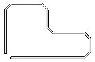
( Toolbar: Modify > Chamfer Ribbon: Modify > Chamfer (in Modify) Menu: Modify > Chamfer Keyboard: _CHAMFER Alias: CHA Experience Level: Intermediate Creates a chamfer, or a beveled edge, at the intersection of two 3D solids, lines, rays, or infinite lines. If the entities you want to chamfer do not intersect, they are trimmed or extended until they can be chamfered.
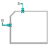
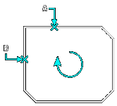
If both entities are on the same layer, the chamfer is drawn on that layer. If the entities whose intersection will form the chamfer are on two different layers, the chamfer is drawn on the current layer. Chamfer (dist1=n, dist2=n): Settings/Polyline/<Select first entity>: To create a simple chamferSelect the first of the two entities whose intersection will be chamfered. Select second entity: To chamfer the intersection between the first and second selected entities, select the second entity. If the entities selected are segments of a closed polyline, you can chamfer all intersections between the first and second selection in the direction in which the segments were created. Note that CADdirect displays a different prompt when it detects that your first selection was a segment in a closed polyline: Directional/<Select second entity>: Choose Directional and press Enter; then select the second entity.
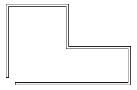
To chamfer all vertices of a polylineYou can chamfer all connected segments of a polyline. Choose Polyline. Select 2D polyline to chamfer: Select the polyline to chamfer. All intersecting edges of the polyline are chamfered.
NOTE If the polyline segments are separated by a connected line or arc that is not part of the polyline, that segment is ignored. To change the chamfer settingsChoose Settings. The Drawing Settings dialog box appears with the Entity Modification tab selected and the current settings for Chamfer/Fillet displayed. Make the changes you want, and then click OK to exit the dialog box and return to your drawing. To change the chamfer distancesYou can change the amount by which each entity trimmed or extended to accommodate the chamfer.
NOTE You can use the TRIMMODE system variable to remove or retain the edges from the endpoints of the chamfer lines. To retain the edges, set the TRIMMODE variable to 0; to remove the edges, set the TRIMMODE variable to 1. To chamfer a 3D solidSelect the edge to chamfer. (One of two surfaces adjacent to the selected edge will be highlighted.) To select a different surface, choose Next and press Enter. Or, to use the current surface, press Enter. Enter chamfer distance for the base surface (measured from the selected edge on the base surface). Enter chamfer distance for the adjacent surface (measured from the selected edge on the adjacent surface). Specify the edges to chamfer, or to select all edges around the base surface, choose Loop and press Enter. Tell me about...How do I... |
|
 )
)


© Copyright 2023. Back2CAD Technologies LLC. All rights reserved. Kazmierczak® is a registered trademark of Kazmierczak Software GmbH. Print2CAD, CADdirect, CAD.direct, CAD Direct, CAD.bot, CAD Bot, are Trademarks of BackToCAD Technologies LLC. DWG is the name of Autodesk’s proprietary file format and technology used in AutoCAD® software and related products. Autodesk, the Autodesk logo, AutoCAD, DWG are registered trademarks or trademarks of Autodesk, Inc. All other brand names, product names, or trademarks belong to their respective holders. This website is independent of Autodesk, Inc., and is not authorized by, endorsed by, sponsored by, affiliated with, or otherwise approved by Autodesk, Inc. The material and software have been placed on this Internet site under the authority of the copyright owner for the sole purpose of viewing of the materials by users of this site. Users, press or journalists are not authorized to reproduce any of the materials in any form or by any means, electronic or mechanical, including data storage and retrieval systems, recording, printing or photocopying.
|