Multiple Insert: MINSERT |
|
|
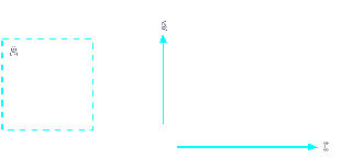
Keyboard: _MINSERT Creates a rectangular pattern from multiple copies of a block. Copies of the block are placed up and to the right from the point you specify. 
? to list blocks in drawing ◆ BROWSE ◆ EXPLORE ◆ <Block to insert> < >: Type the name of the block to insert, or press Enter to place the current block (if displayed). To list all blocks in the current drawing, choose ?. To insert a block that you have saved to disk, choose Browse. To display CADdirect's Explorer with a list of blocks in the active drawing, choose Explore. Multiple blocks ◆ <Insertion point for block>: Select the insertion point for the block, the default selection. To insert multiple copies of the block in a rectangular pattern, choose Multiple. To insert a block in a rectangular patternSelect the insertion point for the block. Done ◆ XYZ ◆ X scale factor <1.0000>: To accept the current value for the x scale factor, press Enter. To use another value, type a number. To insert the block without changing the x,y,z scale factors, choose Done. Y scale factor: <Equal to X scale (1.0000)>: To accept the current value for the y scale, press Enter. To use another value, type a number. Rotation angle for block <0 >: To accept the current value for the rotation angle, press Enter. To use another value, type a number. This value sets the rotation angle of both individual blocks and an array of blocks. Number of rows in the array <1>: Enter the number of rows of blocks to create. Number of columns <1>: Enter the number of columns of blocks to create. If the value for the number of rows or columns is greater than 1, the following prompts appear: Vertical distance between rows, or spacing rectangle: Enter the distance you want between rows by typing a value or by specifying two points on the screen. Horizontal distance between columns: Enter the distance you want between columns by typing a value or by specifying two points on the screen. To insert multiple copies of the same rectangular patternChoose Multiple. Insertion point for first block: Place the first block in the pattern by selecting a point on the screen. Done ◆ XYZ ◆ X scale factor <1.0000>: To accept the current value for the x scale factor, press Enter. To use another value, type a number. To insert the block without changing the x,y,z scale factors, choose Done. Number of rows in the array <1>: Enter the number of rows of blocks to create. Number of columns <1>: Enter the number of columns of blocks to create. If the value for the number of rows or columns is greater than 1, the following prompts appear: Vertical distance between rows, or spacing rectangle: Enter the distance you want between rows by typing a value or by specifying two points on the screen. Horizontal distance between columns: Enter the distance you want between columns by typing a value or by specifying two points on the screen. Insertion point for next block: Place the next pattern of blocks by selecting a point on the screen. Another rectangular array of blocks is drawn just like the first one. Continue inserting this pattern by selecting insertion points. To end the command, right-click the mouse or press Esc. To insert a block that was saved to diskChoose Browse. The Insert Block dialog box is displayed. Find the block from which you want to create a rectangular pattern, and then click Open. To use the Explorer to locate a saved blockChoose Explore. The Explorer is displayed with the Blocks group active. Double-click a block to begin placing a rectangular pattern. Tell me about...How do I... |

|
© Copyright 2023. Back2CAD Technologies LLC. All rights reserved. Kazmierczak® is a registered trademark of Kazmierczak Software GmbH. Print2CAD, CADdirect, CAD.direct, CAD Direct, CAD.bot, CAD Bot, are Trademarks of BackToCAD Technologies LLC. DWG is the name of Autodesk’s proprietary file format and technology used in AutoCAD® software and related products. Autodesk, the Autodesk logo, AutoCAD, DWG are registered trademarks or trademarks of Autodesk, Inc. All other brand names, product names, or trademarks belong to their respective holders. This website is independent of Autodesk, Inc., and is not authorized by, endorsed by, sponsored by, affiliated with, or otherwise approved by Autodesk, Inc. The material and software have been placed on this Internet site under the authority of the copyright owner for the sole purpose of viewing of the materials by users of this site. Users, press or journalists are not authorized to reproduce any of the materials in any form or by any means, electronic or mechanical, including data storage and retrieval systems, recording, printing or photocopying.
|