|
Layout Viewports: MVIEW |
|
|
( Toolbar: Viewport > Layout Viewports Ribbon: View > Layout Viewports (in Layouts) Menu: View > Viewports > Layout Viewports Keyboard: _MVIEW Alias: MV Experience Level: Intermediate The Layout Viewports command creates and controls views of your drawing from a Layout tab. You must click a Layout tab before you use the Layout Viewports command. If this is the first time using that Layout tab, your drawing disappears. This is normal. You must create at least one layout viewport to see your drawing. The number of viewports you can create is limited only by your system resources. 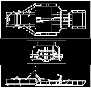
An example of multiple viewports. Viewports: ON ◆ OFF ◆ Fit ◆ Lock ◆ Entity ◆ Polygonal ◆ 2 ◆ 3 ◆ 4 ◆ <First corner>: Specify the first corner of the layout viewport. To turn layout viewports on, choose ON. To turn layout viewports off, choose OFF. To create a layout viewport that fills the screen, choose Fit. To lock the viewport scale and view in model space when panning or zooming in the layout viewport, choose Lock. To create a non-rectangular viewport, choose Polygonal. To create two horizontal or vertical layout viewports, choose 2. To create three horizontal or vertical layout viewports, choose 3. To create four horizontal or vertical layout viewports, choose 4. To define the boundaries of a layout viewportSpecify the first corner of the layout viewport. Opposite corner: Specify the opposite corner of the layout viewport. To turn layout viewports on or offChoose ON or OFF. Select viewports to turn on[off]: Select the edge of the layout viewport to turn on or off, and then press Enter. Doing this does not delete the layout viewport; it simply turns it off. To create a layout viewport that fills the screenChoose Fit to view. To lock or unlock layout viewportsChoose Lock. Viewport View Locking [ON/OFF]: Choose On to lock the viewport scale and view in model space when panning or zooming in the layout viewport. Choose Off to unlock the viewport scale and view. To create a viewport from a closed entityChoose Entity. Select entity to clip viewport: Select a circle, ellipse, closed polyline, spline, or region that you want to convert to a viewport. To create a non-rectangular viewportChoose Polygonal. Start of polyline: Select the start point of the polyline you want to use for the non-rectangular viewport. Arc/Distance/Follow/Halfwidth/Width/Undo/<Next point>: Select the next point of the polyline. To draw an arc as a polyline segment, choose Arc. To specify the length of the next polyline segment, choose Distance. To continue the polyline in the direction of the last entity you drew, choose Follow. To specify the halfwidth of the following polyline segments, choose Halfwidth. To specify the width of the following polyline segments, choose Width. Continue to draw polyline segments by selecting points or options in the command bar. When you are finished, right-click or press Enter to close the polyline and end the command. To create an additional non-rectangular viewport: Choose Polygonal. ENTER to use last point/Follow/<Start of polyline>: Select the start point of the polyline you want to use for the non-rectangular viewport, choose Follow to use the direction of the last entity you drew, or press Enter to use the last point you selected. To create multiple horizontal or vertical layout viewports
Choose Create 2 viewports Two [Three] [Four] viewports: Horizontal ◆ <Vertical>: To create vertical layout viewports, choose Vertical or press Enter. To create horizontal layout viewports, choose Horizontal. Fit to screen ◆ <First corner of bounding rectangle>: Specify the first corner of the layout viewport. To divide the screen into two layout viewports of the same size, choose Fit to screen. To create three viewports
Choose Create 3 viewports. Three viewports ◆ Horizontal ◆ Vertical ◆ Above ◆ Below ◆ Left ◆ <Right>: To create one large layout viewport on the right and two smaller layout viewports on the left, choose Right. To create three horizontal layout viewports of the same size, choose Horizontal. To create three vertical layout viewports of the same size, choose Vertical. To create one large layout viewport on top and two smaller layout viewports on the bottom, choose Above. To create one large layout viewport on the bottom and two smaller layout viewports on top, choose Below. To create one large layout viewport on the left and two smaller layout viewports on the right, choose Left. Fit to screen ◆ <First corner of bounding rectangle>: Specify the first corner of the layout viewport. To create three layout viewports that fill the screen, choose Fit to screen. To create four layout viewports
Four layout viewports Choose Create 4 viewports. Fit to screen ◆ <First corner of bounding rectangle>: Specify the first corner of the layout viewport. To divide the screen into four layout viewports of the same size, choose Fit to screen. Tell me about...How do I... |

|
 )
)
© Copyright 2023. Back2CAD Technologies LLC. All rights reserved. Kazmierczak® is a registered trademark of Kazmierczak Software GmbH. Print2CAD, CADdirect, CAD.direct, CAD Direct, CAD.bot, CAD Bot, are Trademarks of BackToCAD Technologies LLC. DWG is the name of Autodesk’s proprietary file format and technology used in AutoCAD® software and related products. Autodesk, the Autodesk logo, AutoCAD, DWG are registered trademarks or trademarks of Autodesk, Inc. All other brand names, product names, or trademarks belong to their respective holders. This website is independent of Autodesk, Inc., and is not authorized by, endorsed by, sponsored by, affiliated with, or otherwise approved by Autodesk, Inc. The material and software have been placed on this Internet site under the authority of the copyright owner for the sole purpose of viewing of the materials by users of this site. Users, press or journalists are not authorized to reproduce any of the materials in any form or by any means, electronic or mechanical, including data storage and retrieval systems, recording, printing or photocopying.
|