|
Tablet: TABLET |
|
|
Menu: Tools > Tablet Keyboard: _TABLET Alias: TA Shortcut: F4 Controls tablet configuration for tool selection and calibration for digitizer input. CADdirect supports digitizer tablets compatible with the Wintab driver and comes with its own tablet overlay. For instructions on installing the tablet driver and using the buttons on your pointing device, refer to your hardware documentation. For instructions on customizing the overlay menu choices and tablet buttons, see Customizing the tablet interface. Three options are available with the Tablet command:
Before you beginSlip the tablet overlay underneath the tablet's plastic cover and align in accordance with the directions for your tablet. Tablet: ON/OFF/CALibrate/ConFiGure/<On>: To configure the tablet for menu inputType CFG or choose Configure. Do you want to align the tablet overlay? Yes/No/<No>: If your tablet is 12" x 12", CADdirect provides a default configuration. To accept the default, choose No. NOTE If you choose the default configuration, make sure the commands in the grid are being correctly activated. If the default alignment does not work for your tablet, reconfigure the tablet and answer Yes to align the tablet overlay yourself. Digitize upper left corner of the overlay: Click the tablet pointer on the upper left alignment point of the overlay ( Digitize lower left corner of the overlay: Click the tablet pointer on the lower left alignment point of the overlay ( Digitize lower right corner of the overlay: Click the tablet pointer on the lower right alignment point of the overlay ( Digitize lower left corner of the Screen Pointing Area: Click the tablet pointer on the lower left alignment point of the WORKSPACE area of the overlay ( Digitize upper right corner of the Screen Pointing Area: Click the tablet pointer on the upper right alignment of the WORKSPACE area of the overlay ( 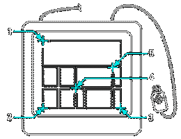
Click points in the order shown to configure your tablet for menu input. NOTE To use the tablet for tool selection, tablet mode must be turned off. To turn tablet mode on or offType ON or OFF or choose On or Off. You can also press the F4 key to toggle tablet mode on or off or double-click TABLET on the status bar. To calibrate your tablet for digitizing pointsYou must specify at least two points for tablet calibration. However, the more points you specify, the more accurate the transformation between the tablet and the screen points. Specifying additional points is particularly useful if you plan to trace a paper drawing that is not orthogonal, such as an aerial photograph. You can specify a maximum of 10 points. Type CAL or choose Calibrate. Digitize point # 1: Click a point on the tablet to define as the first calibration point. Enter coordinates for point # 1: Specify a point within the CADdirect drawing window to correspond to the point you digitized on the tablet, or enter coordinate values in the command bar. Digitize point # 2: Click a point on the tablet to define as the second calibration point. Enter coordinates for point # 2: Specify a point within the CADdirect drawing window to correspond to the point you digitized on the tablet, or enter coordinate values in the command bar. Digitize point # [3-10] (or ENTER to end>: To specify more than the two points required, click a point on the tablet to define as the third calibration point. You can enter up to 10 points. Enter coordinates for point # [3-10]: Specify a point within the CADdirect drawing window to correspond to the point you placed on the tablet, or enter coordinate values in the command bar. Select Transformation type: Orthogonal/Affine/Projective: Type O, A, or P, as appropriate. Depending on the number of points specified, you have a choice of transformation types to use, along with the type recommended by CADdirect. Transformation refers to the calculation of the points on the screen that correspond to points you digitize on the tablet.
Choose the recommended type unless you know it will not be appropriate for what you are digitizing. The most appropriate type is not always the one with the least error; for example, you might digitize three points and select the orthogonal transformation, even though the affine transformation would yield a closer representation of your calibration entries. Example 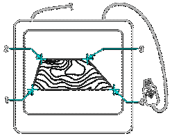
Digitizing on tablet. 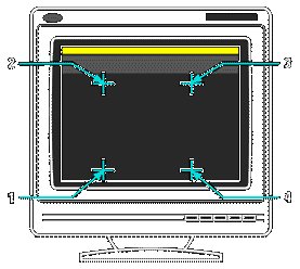
Corresponding coordinates:
Tell me about... |

|
 ).
). 

© Copyright 2023. Back2CAD Technologies LLC. All rights reserved. Kazmierczak® is a registered trademark of Kazmierczak Software GmbH. Print2CAD, CADdirect, CAD.direct, CAD Direct, CAD.bot, CAD Bot, are Trademarks of BackToCAD Technologies LLC. DWG is the name of Autodesk’s proprietary file format and technology used in AutoCAD® software and related products. Autodesk, the Autodesk logo, AutoCAD, DWG are registered trademarks or trademarks of Autodesk, Inc. All other brand names, product names, or trademarks belong to their respective holders. This website is independent of Autodesk, Inc., and is not authorized by, endorsed by, sponsored by, affiliated with, or otherwise approved by Autodesk, Inc. The material and software have been placed on this Internet site under the authority of the copyright owner for the sole purpose of viewing of the materials by users of this site. Users, press or journalists are not authorized to reproduce any of the materials in any form or by any means, electronic or mechanical, including data storage and retrieval systems, recording, printing or photocopying.
|