You can copy an entity in a pattern that creates an array. There are several ways to create arrays:
• Linear array — Use the Copy command to control the number of copies in the array and the line along which the copies are placed.
• Rectangular array — Use the Rectangular Array command to control the number of copies in the array by specifying the number of rows and columns. You also specify the distance between each row and column.
• Polar (circular) array — Use the Polar Array command to control the number of copies that compose the array and whether to rotate the copies.
• Path array — Use the Path Array command to control the number of copies that compose the array and whether to rotate the copies.
Rectangular, polar, and path arrays can be associative, which means the individual entities contained in the array relate to one another and behave more like a block or group. Associative arrays can be easily edited using the Edit Array command.
To create a linear array
1 Do one of the following to choose Copy ( ):
):
• On the ribbon, choose Edit > Copy (in Modify).
• On the menu, choose Modify > Copy.
• On the Modify toolbar, click the Copy tool.
• Type copy and then press Enter.
2 Select the entities, and then press Enter.
3 Specify the start point of the line along which you want to place entities.
4 Choose Array.
5 Enter the number of items in the array, then press Enter.
6 Specify the second point of the line along which you want to place entities; this is the point where the first entities in the array will be placed. Or if you choose Fit, it is the point where the last entities in the array will be placed.
7 Continue specifying points to place additional copies if desired, or press Enter when done.
To create a rectangular array
1 Do one of the following to choose Rectangular Array ( ):
):
• On the ribbon, choose Home > Rectangular Array (in Modify) or Edit > Rectangular Array (in Modify).
• On the menu, choose Modify > Rectangular Array.
• On the Modify toolbar, click the Rectangular Array tool.
• Type arrayrect and then press Enter.
2 Select the entities to include in the array, and then press Enter.
3 Accept the default settings by pressing Enter again or continue with the next steps.
4 If you want to create an array with associative entities, choose Associative, then choose Yes.
5 To specify a new base point for the array, choose Base Point, then specify a new base point for the array in the drawing.
6 To specify the number of rows and columns (a rectangular array must have at least two rows or two columns), do any of the following:
• Choose Count, enter the number of columns, then enter the number of rows.
• Choose Columns, enter the number of columns, then specify the amount of horizontal space you want between each column in the array.
• Choose Rows, enter the number of rows, then enter the amount of vertical space you want between each row in the array, then enter the increasing or decreasing elevation for each subsequent row.
7 To specify spacing between columns or rows directly in the drawing, do the following:
• Choose Spacing.
• Choose Unit cell.
• Select two corners of a rectangle that represents the vertical and horizontal distance between rows and columns.
8 To specify the number of levels, choose Levels, enter the number of levels, then enter the amount of space you want between each level in the array. Positive and negative values create levels in opposite directions along the z-axis.
|
|
|
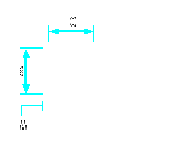
To create a rectangular array, select the entity to copy (A), type the number of rows and columns, and then specify the distance between each row (B) and column (C).
|
To create a polar array
1 Do one of the following to choose Polar Array ( ):
):
• On the ribbon, choose Home > Polar Array (in Modify) or Edit > Polar Array (in Modify).
• On the menu, choose Modify > Polar Array.
• On the Modify toolbar, click the Polar Array tool.
• Type arraypolar and then press Enter.
2 Select the entities to include in the array, and then press Enter.
3 Select the center point around which you want the entities arrayed.
4 Accept the default settings by pressing Enter again or continue with the next steps.
5 If you want to create an array with associative entities, choose Associative, then choose Yes.
6 To specify a new base point for the array, choose Base Point, then specify a new base point for the array in the drawing.
7 Specify two of the following values:
• Items — Enter the number of items to create in the array, including one for the original selection set.
• Fill angle — Enter the angle the array will fill: 0 to 360 degrees. The default setting for the angle is 360 degrees. Positive values create the array in a counterclockwise direction; negative values create the array in a clockwise direction.
• Angle between — Enter the angle between the arrayed items. The default setting is 90 degrees.
8 To specify the number of rows, do the following:
• Choose Rows.
• Enter the number of rows.
• Enter the amount of vertical space you want between each row in the array.
• Enter the incrementing elevation between rows. The default value 0 creates a two-dimensional array. Positive values create each subsequent row with an increasing elevation; negative values create each subsequent row with a decreasing elevation.
9 To set automatic orientation of items in the array, choose Rotate, then choose Yes. Automatic rotation orients subsequent items to match the angle of the path curve.
10 To specify the number of levels, choose Levels, enter the number of levels, then enter the amount of space you want between each level in the array. Positive and negative values create levels in opposite directions along the z-axis.
|
|
|
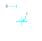
To create a polar array, select the entity to copy (A), specify the center point of the array (B), and then specify other options.
|
To create a path array
1 Do one of the following to choose Path Array ( ):
):
• On the ribbon, choose Home > Path Array (in Modify) or Edit > Path Array (in Modify).
• On the menu, choose Modify > Path Array.
• On the Modify toolbar, click the Path Array tool.
• Type arraypath and then press Enter.
2 Select the entities, and then press Enter.
3 Select a line, polyline, three-dimensional polyline, spline, helix, arc, circle, or ellipse to use for the path of the array.
4 Accept the default settings by pressing Enter again or continue with the next steps.
5 To specify a new base point for the array, choose Base Point, then specify a new base point for the array in the drawing.
6 To specify the distribution of array items along the path, choose Method, then do one of the following:
• Choose Divide to place a specified number of copies that are evenly distributed along the entire length of the path.
• Choose Measure to place copies along the path at a specified distance between them.
7 To specify the alignment of arrayed items relative to the start direction of the path, choose Tangent Direction, then do the following:
• Specify the first point on the entity. Or choose Normal to align the z- direction of the first item with the starting direction of the path.
• Specify the second point on the entity.
8 To specify the number of items in the array, choose Items. The prompts that follow depend on the setting selected in Method:
• Specify number of items: Specify the number of copies of selected entities you want in the array. Displays if Divide is the Method setting.
• Specify the distance between items: Enter the distance to use between arrayed entities. Displays if Measure is the Method setting.
• Enter number of items: The maximum number of items required to fill the entire length of the path is automatically calculated. You can specify a smaller number of items if needed.
9 To specify the number of rows, do the following:
• Choose Rows.
• Enter the number of rows.
• Enter the amount of vertical space you want between each row in the array.
• Enter the incrementing elevation between rows. The default value 0 creates a two-dimensional array. Positive values create each subsequent row with an increasing elevation; negative values create each subsequent row with a decreasing elevation.
10 To specify the alignment of arrayed items relative to each other, choose Align Items, then choose Yes to make all items follow the alignment of the path, or choose No to specify a parallel alignment of arrayed items.
11 To maintain the z-direction of arrayed items, choose Z Direction, then choose Yes to make all items follow the z-direction of the path, or choose No to specify a parallel alignment of arrayed items in the z- direction.
12 To specify the number of levels, choose Levels, enter the number of levels, then enter the amount of space you want between each level in the array. Positive and negative values create levels in opposite directions along the z-axis.
|
|
|
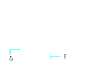
To create a path array, select the entity to copy (A), select the path (B), and then specify other options.
|
To edit an associative array
1 Do one of the following to choose Edit Array ( ):
):
• On the ribbon, choose Home > Edit Array (in Modify) or Edit > Edit Array (in Modify).
• On the menu, choose Modify > Edit Array.
• On the Modify toolbar, click the Edit Array tool.
• Type arrayedit and then press Enter.
2 Select the array you want to edit.
3 To edit the array by modifying one of its arrayed items, do the following:
• Choose Edit Source.
• Select one of the items in the array.
• Modify the item as you would modify any entity in the drawing. You can also create new entities to include them in the source array item.
4 To edit the array by replacing its items with other entities, do the following:
• Choose Replace Item.
• Select new source entities to use as a replacement.
• Specify a base point for placing each replacement entity in the array.
• Select the array item that you want to replace with the new source entities. Continue selecting array items for replacement. Or choose Source entities to replace all array items with the new source entities.
5 To reverse modifications, choose Reset Array, which reverses edits one by one.
6 Continue editing the array. The options vary depending on the type of array you are editing, and most editing options are the same as the array creation options described previously.
7 When finished, click Close Array ( ) on the ribbon (if the ribbon is supported in your program version) or choose Exit.
