When entity snap tracking is turned on, guides display at specified angles outward from temporary tracking points. This can help you draw and modify entities using the relative position of existing entities, for example, inserting a block with the same y-coordinate of an existing line.
Temporary tracking points are marked with a red plus sign, and can be placed anywhere in the drawing. To select where tracking points display, first activate a command that requests a point, then:
• Move the cursor and hover over an entity snap point to add a tracking point.
• Choose the Temporary Tracking Point command, then select anywhere in the drawing for the tracking point to reside.
• Move the cursor and hover over an existing tracking point to remove a tracking point.
You can set up entity snap tracking to display guides at 90-degree increments or additional increments that are defined for polar tracking. You can also set up entity snap tracking to display guides relative to the current UCS or relative to the last segment drawn.
To use entity snap tracking, at least one entity snap must be turned on and running snaps cannot be turned off. Polar tracking does not have to be turned on in order to use entity snap tracking.
To turn entity snap tracking on or off
1 Do one of the following to choose Drawing Settings ( ):
):
• On the ribbon, choose Application button > Drawing Utilities; Home > Drawing Settings (in Utilities); or Tools > Drawing Settings (in Manage).
• On the menu, choose Tools > Drawing Settings.
• On the Tools toolbar, click the Drawing Settings tool.
• Type dsettings and then press Enter.
2 Click the Coordinate Input tab.
3 Click the Entity Snaps tab.
4 Click the Entity Snap Tracking checkbox.
Toggle entity snap tracking on and off.
Double-click the Entity Snap Tracking On/Off on the status bar, type ENTTRACK, or press F11.
|
|
|
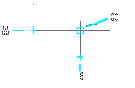
Start a command, hover over one or more entity snap points to mark them with a tracking point (A then B), then move the cursor to view the guides (C). In this example, the Midpoint Snap is turned on and entity snap tracking displays at 90-degree increments.
|
To specify settings for entity snap tracking
1 Do one of the following to choose Drawing Settings ( ):
):
• On the ribbon, choose Application button > Drawing Utilities; Home > Drawing Settings (in Utilities); or Tools > Drawing Settings (in Manage).
• On the menu, choose Tools > Drawing Settings.
• On the Tools toolbar, click the Drawing Settings tool.
• Type dsettings and then press Enter.
2 Click the Coordinate Input tab.
3 Click the Polar Tracking tab.
4 Select one of the following to specify entity tracking settings:
• Orthogonal Only 90-degree angle increments are used for entity snap tracking, regardless of polar tracking settings.
• Use all polar tracking angles All defined polar tracking angles, including those other than 90-degree angle increments, are used for entity snap tracking.
5 Select one of the following to specify how the angles of guides are calculated for entity snap tracking:
• Absolute Guides display at angles relative to the current UCS.
• Relative to last segment Guides display at angles relative to the last segment drawn, if creating entities with multiple segments (otherwise guides display at absolute angles).
6 Click OK.
See also...
Using polar tracking
Temporary Tracking Point tool