You can extend entities so that they end at a boundary defined by other entities. You can also extend entities to the point at which they would intersect an implied boundary edge. When extending entities, you first select the boundary edges, and then specify the entities to extend, selecting them either one at a time, using the fence selection method, or the projection selection method.
You can extend arcs, lines, two-dimensional polylines, and rays. Arcs, circles, ellipses, lines, splines, polylines, rays, infinite lines, and viewports on a Layout tab can act as boundary edges.
To extend an entity
1 Do one of the following to choose Extend ( ):
):
• On the ribbon, choose Edit > Extend (in Modify).
• On the menu, choose Modify > Extend.
• On the Modify toolbar, click the Extend tool.
• Type extend and then press Enter.
2 Select one or more entities as boundary edges, and then press Enter.
3 Select the entity to extend.
4 Select another entity to extend, or press Enter to complete the command.
To extend an entity to an implied boundary
1 Do one of the following to choose Extend ( ):
):
• On the ribbon, choose Edit > Extend (in Modify).
• On the menu, choose Modify > Extend.
• On the Modify toolbar, click the Extend tool.
• Type extend and then press Enter.
2 Select one or more boundary edges, and then press Enter.
3 In the prompt box, choose Edge Mode.
4 In the prompt box, choose Extend.
5 Select the entity to extend.
6 Select another entity to extend, or press Enter to complete the command.
|
|
|
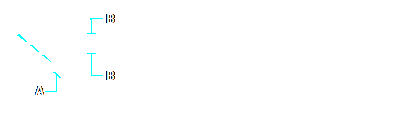
Select the boundary edge (A), and then select the entities to extend (B).
|
|
Result.
|
To extend several entities using the fence selection method
1 Do one of the following to choose Extend ( ):
):
• On the ribbon, choose Edit > Extend (in Modify).
• On the menu, choose Modify > Extend.
• On the Modify toolbar, click the Extend tool.
• Type extend and then press Enter.
2 Select one or more boundary edges, and then press Enter.
3 In the prompt box, choose Fence.
4 Specify the first point of the fence.
5 Specify the second point of the fence.
6 Specify the next fence point, or press Enter to complete the command.
When you extend a wide polyline, its centerline intersects the boundary edge. Because the end of the polyline is always cut at a 90-degree angle, part of the polyline may extend past the boundary edge. A tapered polyline continues to taper until it intersects the boundary edge. If this would result in a negative polyline width, the ending width changes to 0.
|
|
|
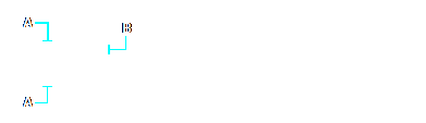
A tapered polyline (A) continues to taper until it intersects the boundary edge (B).
|
|
Result.
|
