BackToCAD Technologies LLC | Artificial Intelligence and Software Developing | Clearwater, USA; Stuttgart, Germany | Kazmierczak® Company
Adding geometric tolerances
Geometric tolerances indicate the maximum allowable variations in the geometry defined by a drawing. CADdirect 2022 draws geometric tolerances using a feature control frame, which is a rectangle divided into compartments.
Understanding geometric tolerances
Each feature control frame consists of at least two compartments. The first compartment contains a geometric tolerance symbol that indicates the geometric characteristic to which the tolerance is applied, such as location, orientation, or form. For example, a form tolerance may indicate the flatness or roundness of a surface. The geometric tolerance symbols and their characteristics are shown in the following table.
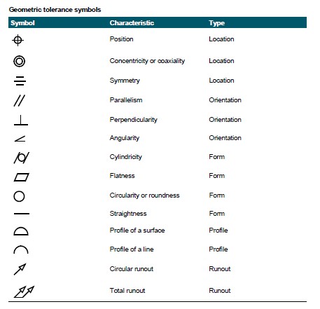
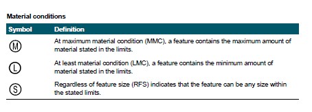
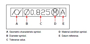
The second compartment contains the tolerance value. When appropriate, the tolerance value is preceded by a diameter symbol and followed by a material condition symbol. The material conditions apply to features that can vary in size. The material condition symbols and their meanings are shown in the following table.
The tolerance value can then be followed by primary, secondary, and tertiary datum reference letters, along with the material conditions of each datum. Datum reference letters are generally used as reference tolerances to one of up to three perpendicular planes from which a measurement is made, although datum reference letters can also indicate an exact point or axis.
When two tolerances apply to the same geometry, you can also add a composite tolerance consisting of a primary tolerance value followed by a secondary tolerance value. To make a tolerance even more specific, it can also contain a projected tolerance consisting of a height value followed by a projected tolerance symbol. For example, you can use a projected tolerance to indicate the perpendicularity of an embedded part.
Adding a geometric tolerance
To add a geometric tolerance
Do one of the following to choose Tolerance:
- On the ribbon, choose Annotate > Tolerance (in Dimensions).
- On the menu, choose Dimensions > Tolerance.
- On the Dimensioning toolbar, click the Tolerance tool.
- Type tolerance and then press Enter.
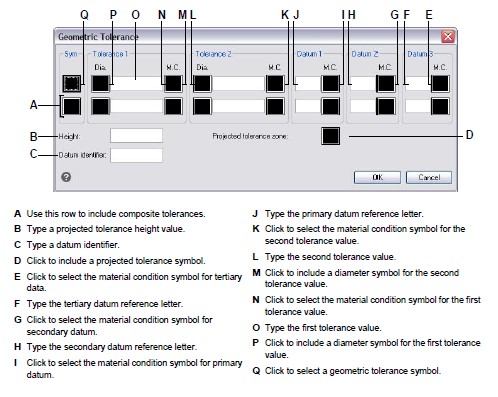
To display the geometric tolerance symbols, on the first line, click the Sym box.
Click to select a geometric tolerance symbol.
Under Tolerance 1, click the Dia box to add a diameter symbol.
In the field, type the first tolerance value.
To display the material condition symbols, click the M.C. box.
Click to select a material condition.
Under Tolerance 2, repeat steps 4 through 7 to add a secondary tolerance value, if appropriate.
Under Datum 1, type the primary datum reference letter.
To display the material condition symbols, click the M.C. box.
Click to select a material condition.
Repeat steps 9 through 11 to add secondary and tertiary datum, if appropriate.
In the second row, repeat steps 2 through 12 to add composite tolerances, if appropriate.
In the Height box, type a projected tolerance zone height value, if appropriate.
To insert a projected tolerance zone symbol, click the Projected Tolerance Zone box, if appropriate.
Click OK.
In the drawing, specify the location of the feature frame.
Controlling dimension tolerances
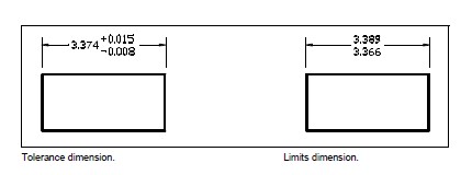
You can create dimensions as either tolerance or limits dimensions. When creating a tolerance dimension, you can control the upper and lower tolerance limits as well as the number of decimal places of the dimension text. The image tile on the right side of the Dimension Styles dialog box shows the appearance of tolerance and limits dimensions based on the current dimension style settings.
To control dimension tolerances
Do one of the following to choose Dimension Styles Manager:
- On the ribbon, choose Annotate > Dimension Styles Manager (in Dimensions).
- On the menu, choose Dimensions > Dimension Styles Manager or choose Format > Dimension Styles Manager.
- On the Dimensioning toolbar, click the Dimension Styles Manager tool.
- Type setdim and then press Enter.
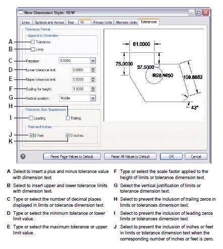
Click the Tolerance tab.
Make your selections.
Click OK.
© Copyright 2021 BackToCAD Technolgies LLC . All rights reserved. Kazmierczak® is a registered trademark of Kazmierczak Software GmbH. CADdirect 2022 is a trademark of Expert Robotics Inc. Print2CAD and CAD2Print are Trademarks of BackToCAD Technologies LLC. DWG is the name of Autodesk’s proprietary file format and technology used in AutoCAD® software and related products. Autodesk, the Autodesk logo, AutoCAD, DWG are registered trademarks or trademarks of Autodesk, Inc., and/or its subsidiaries and/or affiliates in the USA and/or other countries. All other brand names, product names, or trademarks belong to their respective holders. This website is independent of Autodesk, Inc., and is not authorized by, endorsed by, sponsored by, affiliated with, or otherwise approved by Autodesk, Inc. The material and software have been placed on this Internet site under the authority of the copyright owner for the sole purpose of viewing of the materials by users of this site. Users, press, or journalists are not authorized to reproduce any of the materials in any form or by any means, electronic or mechanical, including data storage and retrieval systems, recording, printing or photocopying.