BackToCAD Technologies LLC | Artificial Intelligence and Software Developing | Clearwater, USA; Stuttgart, Germany | Kazmierczak® Company
Chamfering and filleting entities
You can chamfer or fillet entities. A chamfer connects two nonparallel entities with a line to create a beveled edge. A fillet connects two entities with an arc of a specified radius to create a rounded edge. If both entities you are working with are on the same layer, the chamfer or fillet is drawn on that layer. If they are on different layers, the chamfer or fillet is drawn on the current layer.
Modifying the chamfer and fillet settings
The Chamfer/Fillet settings in the Drawing Settings dialog box control the chamfer and fillet settings. The portions of the entities that extend beyond the chamfer or fillet are normally deleted when you create the chamfer or fillet. You can retain these original entities, however, by changing the settings in the dialog box.
To modify the chamfer and fillet settings
Do one of the following to choose Drawing Settings:
- On the ribbon, choose Home > Drawing Settings (in Utilities) or choose Tools > Drawing Settings (in Manage).
- On the menu, choose Tools > Drawing Settings.
- On the Tools toolbar, click the Drawing Settings tool.
- Type settings and then press Enter.
In the Drawing Settings dialog box, click the Entity Modification tab.
In the Change Settings For list, click Chamfer/Fillet and choose from the following:
- Corners — Select to remove or retain portions of entities that extend beyond the chamfer or fillet.
- Fillet radius — Specify the fillet radius or click Select to specify it by selecting two points in the drawing.
- Chamfer Distances and Angles — Choose to use the distance-distance method or distance-angle method when creating chamfers. The distance-distance method creates a chamfer using two chamfer distances that you specify. The distance-angle method creates a chamfer using a chamfer length and angle that you specify.
Click OK.
Chamfering entities
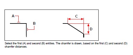
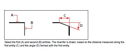
You can connect two nonparallel entities by extending or trimming them and then joining them with a line to create a beveled edge. You can chamfer lines, polylines, rays, and infinite lines. When creating a chamfer, you can specify how far to trim the entities back from their intersection (distance-distance method), or you can specify the length of the chamfer and the angle it forms along the first entity (distance-angle method).
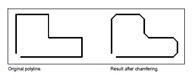
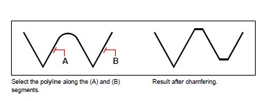
When chamfering a polyline, you can chamfer multiple segments between two selected polyline segments, or you can chamfer the entire polyline.
Chamfering two entities using the distance-distance method
To chamfer two entities using the distance-distance method
Do one of the following to choose Chamfer:
- On the ribbon, choose Modify > Chamfer (in Modify).
- On the menu, choose Modify > Chamfer.
- On the Modify toolbar, click the Chamfer tool.
- Type chamfer and then press Enter.
In the prompt box, choose Chamfer Settings.
In the Drawing Settings dialog box, click the Entity Modification tab.
Under Chamfer Distances And Angles, click Distance-Distance.
Under Chamfer Distances And Angles, specify the first and second chamfer distances.
Click OK.
Select the first entity.
Select the second entity.
Chamfering two entities using the distance-angle method
To chamfer two entities using the distance-angle method
Do one of the following to choose Chamfer:
- On the ribbon, choose Modify > Chamfer (in Modify).
- On the menu, choose Modify > Chamfer.
- On the Modify toolbar, click the Chamfer tool.
- Type chamfer and then press Enter.
In the prompt box, choose Chamfer Settings.
In the Drawing Settings dialog box, click the Entity Modification tab.
Under Chamfer Distances And Angles, click Distance-Angle.
Under Chamfer Distances And Angles, specify the chamfer distance and angle.
Click OK.
Select the first entity.
Select the second entity.
Chamfering all vertices in a polyline
To chamfer all vertices in a polyline
Do one of the following to choose Chamfer:
- On the ribbon, choose Modify > Chamfer (in Modify).
- On the menu, choose Modify > Chamfer.
- On the Modify toolbar, click the Chamfer tool.
- Type chamfer and then press Enter.
In the prompt box, choose Polyline.
Select the polyline.
Chamfering selected vertices in a polyline
To chamfer selected vertices in a polyline
Do one of the following to choose Chamfer:
- On the ribbon, choose Modify > Chamfer (in Modify).
- On the menu, choose Modify > Chamfer.
- On the Modify toolbar, click the Chamfer tool.
- Type chamfer and then press Enter.
Select the polyline along the segment where you want to begin the chamfer.
Select the polyline along the segment where you want to end the chamfer.
Filleting entities
You can connect two entities with an arc of a specified radius to create a rounded edge. You can fillet pairs of line segments, straight polyline segments, arcs, circles, rays, and infinite lines. You can also fillet parallel lines, rays, and infinite lines. When filleting a polyline, you can fillet multiple segments between two selected segments, or you can fillet the entire polyline.
Filleting two entities
To fillet two entities
Do one of the following to choose Fillet:
- On the ribbon, choose Modify > Fillet (in Modify).
- On the menu, choose Modify > Fillet.
- On the Modify toolbar, click the Fillet tool.
- Type fillet and then press Enter.
In the prompt box, choose Fillet Settings.
In the Drawing Settings dialog box, specify the fillet radius.
Click OK.
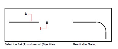
Select the first entity.
Select the second entity.
Filleting an entire polyline
To fillet an entire polyline
Do one of the following to choose Fillet:
- On the ribbon, choose Modify > Fillet (in Modify).
- On the menu, choose Modify > Fillet.
- On the Modify toolbar, click the Fillet tool.
- Type fillet and then press Enter.
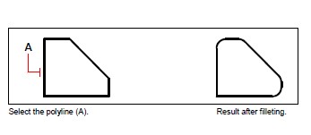
In the prompt box, choose Polyline.
Select the polyline.
Filleting selected vertices in a polyline
To fillet selected vertices in a polyline
Do one of the following to choose Fillet:
- On the ribbon, choose Modify > Fillet (in Modify).
- On the menu, choose Modify > Fillet.
- On the Modify toolbar, click the Fillet tool.
- Type fillet and then press Enter.
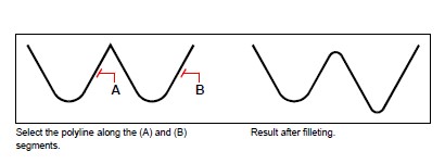
Select the polyline along the segment where you want to begin the fillet.
Select the polyline along the segment where you want to end the fillet.
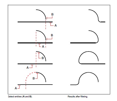
When you fillet circles and arcs, more than one fillet can exist between the entities. The point at which you select the entities determines the fillet.
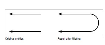
You can fillet parallel lines, rays, and infinite lines. The first entity must be a line or ray; the second entity can be a line, ray, or infinite line. The diameter of the fillet arc is always equal to the distance between the parallel entities. The current fillet radius is ignored.
© Copyright 2021 BackToCAD Technolgies LLC . All rights reserved. Kazmierczak® is a registered trademark of Kazmierczak Software GmbH. CADdirect 2022 is a trademark of Expert Robotics Inc. Print2CAD and CAD2Print are Trademarks of BackToCAD Technologies LLC. DWG is the name of Autodesk’s proprietary file format and technology used in AutoCAD® software and related products. Autodesk, the Autodesk logo, AutoCAD, DWG are registered trademarks or trademarks of Autodesk, Inc., and/or its subsidiaries and/or affiliates in the USA and/or other countries. All other brand names, product names, or trademarks belong to their respective holders. This website is independent of Autodesk, Inc., and is not authorized by, endorsed by, sponsored by, affiliated with, or otherwise approved by Autodesk, Inc. The material and software have been placed on this Internet site under the authority of the copyright owner for the sole purpose of viewing of the materials by users of this site. Users, press, or journalists are not authorized to reproduce any of the materials in any form or by any means, electronic or mechanical, including data storage and retrieval systems, recording, printing or photocopying.