BackToCAD Technologies LLC | Artificial Intelligence and Software Developing | Clearwater, USA; Stuttgart, Germany | Kazmierczak® Company
Copying entities
You can copy one or more entities, making one copy or multiple copies within the current drawing. You can also copy entities between drawings.
Use any of the following methods to copy entities within the current drawing:
- Create a copy at a location referenced from the original.
- Create a copy aligned parallel to the original.
- Create a copy as a mirror image of the original.
- Create several copies in a rectangular or circular pattern.
Copying entities within a drawing
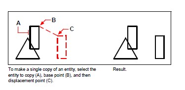
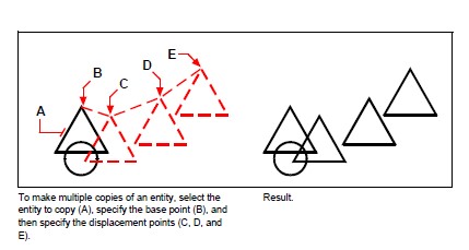
You can duplicate entities within the current drawing. The default method is to create a selection set and then specify a starting point, or base point, and an endpoint, or dis-placement point, for the copy. You can also make multiple copies or copy the selection set to a location you specify, using a direction vector.
To copy a selection set
Do one of the following to choose Copy:
- On the ribbon, choose Edit > Copy (in Modify).
- On the menu, choose Modify > Copy.
- On the Modify toolbar, click the Copy tool.
- Type copy and then press Enter.
Select the entities, and then press Enter.
Specify the base point.
Specify the insertion point
Continue specifying insertion points to place additional copies.
To complete the command, press Enter.
Use a shortcut.
Press and hold Ctrl, then click and drag the left mouse button to copy an entity.
Use a system variable.
The COPYMODE system variable controls whether you are prompted for multiple copies.
Copying between drawings
You can use the Clipboard to cut or copy entities from one drawing to another. Cutting removes the selected entities from a drawing and stores them on the Clipboard. Copying duplicates the selected entities from a drawing and places them on the Clipboard.
To cut entities to the Clipboard
Select the entities you want to cut.
Do one of the following to choose Cut:
- On the ribbon, choose Edit > Cut (in Modify).
- On the menu, choose Edit > Cut.
- On the Standard toolbar, click the Cut tool.
- Type cutclip and then press Enter.
To copy entities to the Clipboard
Select the entities you want to copy.
Do one of the following to choose Copy:
- On the ribbon, choose Home > Copy (in Clipboard).
- On the menu, choose Edit > Copy.
- On the Standard toolbar, click the Copy tool.
- Type copyclip and then press Enter.
Anything that you can copy to the Clipboard can be pasted into a drawing. The format in which the program adds the Clipboard contents to the drawing depends on the type of information in the Clipboard. For example, if you copy CADdirect 2022 drawing entities to the Clipboard, the program pastes them into the drawing as CADdirect 2022 entities. If you copy items to the Clipboard from other programs, they are pasted into the current drawing as embedded ActiveX® objects.
Sometimes the format you want to paste is not available on the Clipboard.
This is mostly likely due to the settings on the Clipboard tab in Tools > Options. For details, see “Changing the options on the Clipboard tab” on page 609.
To paste entities from the Clipboard
Do one of the following to choose Paste:
- On the ribbon, choose Home > Paste (in Clipboard) or choose Edit > Paste (in Modify).
- On the menu, choose Edit > Paste.
- On the Standard toolbar, click the Paste tool.
- Type pasteclip and then press Enter.
Specify the insertion point.
Clipboard contents can also be inserted as a block.
Type pasteblock to convert Clipboard contents into a block upon insertion
Copying between spaces
You can copy entities from model space to paper space or from paper space to model space. You must be viewing a Layout tab that has at least one layout viewport in order to copy entities between spaces. You can also move entities between spaces using the same Change Space command.
For more details about model space and paper space, see “Understanding paper space and model space” on page 450.
To copy entities between spaces
Click a Layout tab.
Select the entities you want to copy.
Do one of the following to choose Change Space:
- On the ribbon, choose Edit > Change Space (in Modify).
- On the menu, choose Modify > Change Space.
- On the Modify toolbar, click the Change Space tool.
- Type chspace and then press Enter.
Choose Copy.
If using the command bar, the Copy option can get confused with crossing selections.
To use the Crossing selection method, type the full keyword “crossing”. Typing “c” calls the Copy option.
Making parallel copies
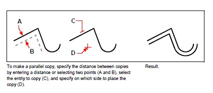
You can use the offset feature to copy selected entities and align them parallel to the original entities at a specified distance. You can make parallel, offset entities using arcs, circles, ellipses, elliptical arcs, lines, two-dimensional polylines, rays, and infinite lines.
Making parallel, offset copies of curved entities creates larger or smaller curves, depending on which side of the original entity you place the copy. For example, placing a parallel copy of a circle outside the circle creates a larger concentric circle; positioning the copy inside the circle creates a smaller concentric circle.
To make a parallel copy by specifying the distance
Do one of the following to choose Offset:
- On the ribbon, choose Edit > Offset (in Modify).
- On the menu, choose Modify > Offset.
- On the Modify toolbar, click the Offset tool.
- Type offset and then press Enter.
Specify the distance by selecting two points or by entering a distance.
Select the entity to copy.
Specify on which side of the entity to place the parallel copy.
Select another entity to copy, or press Enter to complete the command.
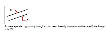
To make a parallel copy passing through a point
Do one of the following to choose Offset:
- On the ribbon, choose Edit > Offset (in Modify).
- On the menu, choose Modify > Offset.
- On the Modify toolbar, click the Offset tool.
- Type offset and then press Enter.
In the prompt box, choose Through Point.
Select the entity to copy.
Specify the point for the entity to pass through.
Repeat steps 3 and 4, or press Enter to complete the command.
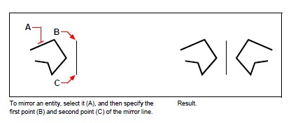
Mirroring entities
You can create a mirror image of an entity. You mirror the entity about a mirror line, which you define by specifying two points in a drawing. You can delete or retain the original entities.
To mirror entities
Do one of the following to choose Mirror:
- On the ribbon, choose Edit > Offset (in Modify).
- On the menu, choose Modify > Mirror.
- On the Modify toolbar, click the Mirror tool.
- Type mirror and then press Enter.
Select the entity, and then press Enter.
Specify the first point of the mirror line.
Specify the second point of the mirror line.
In the prompt box, choose one of the following:
- Yes, Delete Entities – deletes the original entities.
- No, Keep Entities – retains the original entities.
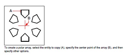
Arraying entities
You can copy an entity in a rectangular or polar (circular) pattern, creating an array. For a rectangular array, you control the number of copies in the array by specifying the number of rows and columns. You also specify the distance between each row and column. For a polar array, you control the number of copies that compose the array and whether to rotate the copies.
To create a polar array
Do one of the following to choose Array:
- On the ribbon, Edit > Array (in Modify).
- On the menu, choose Modify > Array.
- On the Modify toolbar, click the Array tool.
- Type array and then press Enter.
Select the entities, and then press Enter.
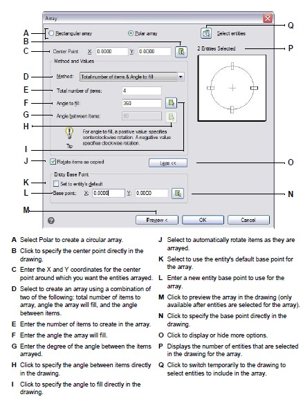
In the Array dialog box, choose Polar Array.
Specify the center point of the array, or click to select the center point in the drawing.
Select the method, which determines the two variables that are used to create the array, then specify the two variables:
- Total number of items — Enter the number of items to create in the array, including one for the original selection set.
- Angle to fill — Enter the angle to fill: 0 to 360 degrees. The default setting for the angle is 360 degrees. Positive values create the array in a counterclockwise direction; negative values create the array in a clockwise direction. You can also click to select the angle in the drawing.
- Angle between items — Enter the angle between lines. The default setting is 90 degrees. You can also click to select the angle in the drawing.
In Rotate Entities as Copied, mark the checkbox to rotate entities as they are arrayed or unmark it to retain the original orientation of each copy as it is arrayed.
To specify a new base point for the array, do the following:
- Click More.
- Unmark Set to Entity’s Default.
- In Base Point, enter a new entity base point to use for the array, or click to select the base point in the drawing.
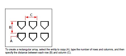
To create a rectangular array
Do one of the following to choose Array:
- On the ribbon, Edit > Array (in Modify).
- On the menu, choose Modify > Array.
- On the Modify toolbar, click the Array tool.
- Type array and then press Enter.
Select the entities, and then press Enter.
In the Array dialog box, choose Rectangular Array.
Enter the number of rows and the number of columns. A rectangular array must have at least two rows or two columns.
In Row Offset, specify the distance between the rows. You can also click to specify the row and column offset at the same time in the drawing, or you can click to select only the row offset.
In Column Offset, specify the distance between the columns. You can also click to specify the row and column offset at the same time in the drawing, or you can click to select only the column offset.
In Angle of Array, enter the angle at which to rotate the array, or click to select the angle directly in the drawing.
© Copyright 2021 BackToCAD Technolgies LLC . All rights reserved. Kazmierczak® is a registered trademark of Kazmierczak Software GmbH. CADdirect 2022 is a trademark of Expert Robotics Inc. Print2CAD and CAD2Print are Trademarks of BackToCAD Technologies LLC. DWG is the name of Autodesk’s proprietary file format and technology used in AutoCAD® software and related products. Autodesk, the Autodesk logo, AutoCAD, DWG are registered trademarks or trademarks of Autodesk, Inc., and/or its subsidiaries and/or affiliates in the USA and/or other countries. All other brand names, product names, or trademarks belong to their respective holders. This website is independent of Autodesk, Inc., and is not authorized by, endorsed by, sponsored by, affiliated with, or otherwise approved by Autodesk, Inc. The material and software have been placed on this Internet site under the authority of the copyright owner for the sole purpose of viewing of the materials by users of this site. Users, press, or journalists are not authorized to reproduce any of the materials in any form or by any means, electronic or mechanical, including data storage and retrieval systems, recording, printing or photocopying.