BackToCAD Technologies LLC | Artificial Intelligence and Software Developing | Clearwater, USA; Stuttgart, Germany | Kazmierczak® Company
Creating dimensions
You can create dimensions by:
- Selecting the entity to dimension and specifying the dimension line location.
- Specifying the extension line origins and the dimension line location.
When you create dimensions by selecting an entity, the program automatically places the extension line origins at the appropriate definition points based on the type of entity you select. For example, the definition points are located at the endpoints of arcs, lines, and polyline segments. When you create dimensions by specifying the extension line origins, the points you specify determine the definition points. To establish these points precisely, use entity snaps.
You can create dimensions in model space or paper space.
Creating linear dimensions
Linear dimensions annotate linear distances or lengths and can be oriented horizon-tally, vertically, or aligned parallel to an existing entity or to the selected extension origin points. After you create a linear dimension, you can add a baseline dimension or a continued dimension. A linear baseline dimension inserts an additional dimension from a common first extension line origin of a previous linear dimension. A linear continued dimension continues a linear dimension from the second extension line of a previous linear dimension.
Selecting exact points is important when creating dimensions.
Use entity snaps to select precise ordinate points.
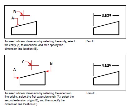
To create a horizontal or vertical dimension
Do one of the following to choose Linear:
- On the ribbon, choose Annotate > Linear (in Dimensions).
- On the menu, choose Dimensions > Linear.
- On the Dimensioning toolbar, click the Linear tool.
- Type dimaligned and then press Enter.
Press Enter, and then select the entity to dimension.
Specify the dimension line location.
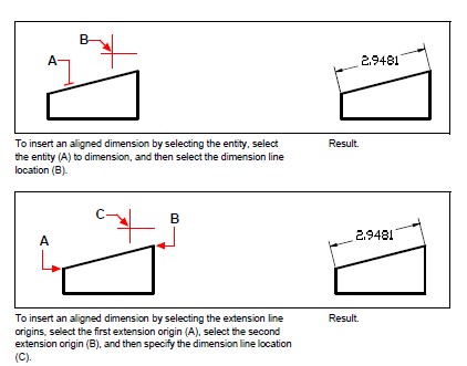
To create an aligned dimension
Do one of the following to choose Aligned:
- On the ribbon, choose Annotate > Aligned (in Dimensions).
- On the menu, choose Dimensions > Aligned.
- On the Dimensioning toolbar, click the Aligned tool.
- Type dimaligned and then press Enter.
Press Enter, and then select the entity to dimension.
Or you can insert the dimension by specifying
the first and second extension line origins.
Specify the dimension line location.
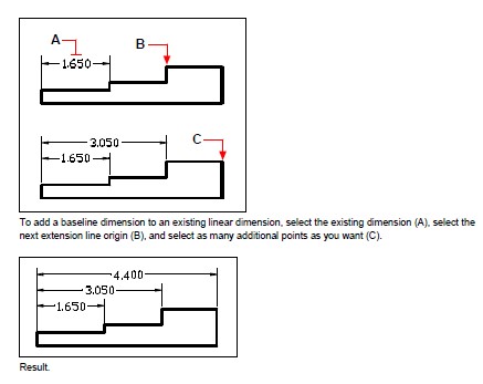
To create a linear baseline dimension
Create a dimension.
Do one of the following to choose Baseline
- On the ribbon, choose Annotate > Baseline (in Dimensions).
- On the menu, choose Dimensions > Baseline.
- On the Dimensioning toolbar, click the Baseline tool.
- Type dimbaseline and then press Enter.
To select a starting dimension, press Enter.
Select the next extension line origin, and then press Enter.
Or press Enter, and then select an existing dimension for the baseline. Select the origin of the next extension line, and then press Enter.
The program automatically places the new baseline dimension above or below the previous dimension line. The distance between the two dimension lines is determined by the Baseline Offset value in the Dimension Styles dialog box.
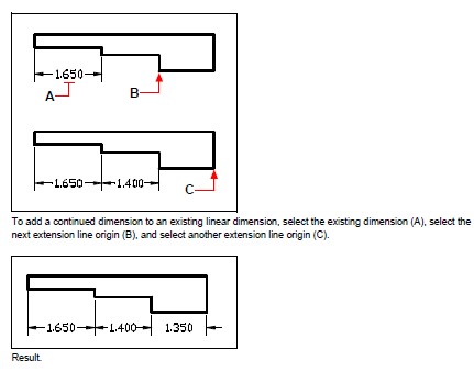
To create a linear continued dimension
Create a dimension.
Do one of the following to choose Continue:
- On the ribbon, choose Annotate > Continue (in Dimensions).
- On the menu, choose Dimensions > Continue.
- On the Dimensioning toolbar, click the Continue tool.
- Type dimcontinue and then press Enter.
To select a starting dimension, press Enter.
Select the next extension line origin, and then press Enter.
Or press Enter, and then select an existing dimension to continue.
To add continued dimensions, continue selecting extension line origins.
To end the command, press Enter twice.
Creating angular dimensions
Angular dimensions annotate the angle measured between two lines. You can also dimension an angle by selecting an angle vertex and two endpoints. After you create an angular dimension, you can add a baseline dimension or a continued dimension. An angular baseline dimension inserts an additional dimension from a common first extension line origin of a previous angular dimension. An angular continued dimension continues an angular dimension from the second extension line of a previous angular dimension.
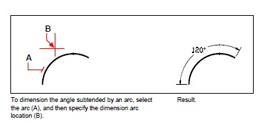
To dimension an angle encompassed by an arc
Do one of the following to choose Angular :
- On the ribbon, choose Annotate > Angular (in Dimensions).
- On the menu, choose Dimensions > Angular.
- On the Dimensioning toolbar, click the Angular tool.
- Type dimangular and then press Enter.
Select the arc.
Specify the dimension arc location.
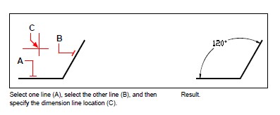
To dimension an angle between two lines
Do one of the following to choose Angular :
- On the ribbon, choose Annotate > Angular (in Dimensions).
- On the menu, choose Dimensions > Angular.
- On the Dimensioning toolbar, click the Angular tool.
- Type dimangular and then press Enter.
Select one line.
Select the other line.
Specify the dimension line location.
Or press Enter, and then select an existing dimension for the baseline. Select the origin of the next extension line, and then press Enter.
The program automatically places the new baseline dimension above or below the previous dimension line. The distance between the two dimension lines is determined by the Baseline Offset value in the Dimension Styles dialog box.
Creating arc dimensions
Arc dimensions annotate the length of an arc or arc segment. You can also dimension a portion of an arc by selecting two points. After you create an arc dimension, you can change its text to the arc angle or to any other text.
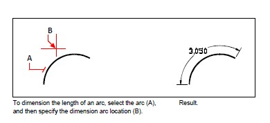
To dimension an arc length
Do one of the following to choose Arc:
- On the ribbon, choose Annotate > Arc (in Dimensions).
- On the menu, choose Dimensions > Arc.
- On the Dimensioning toolbar, click the Arc tool.
- Type dimarc and then press Enter.
Select the arc or arc segment.
Specify the dimension arc location.
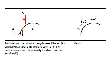
To dimension part of an arc length
Do one of the following to choose Arc :
- On the ribbon, choose Annotate > Arc (in Dimensions).
- On the menu, choose Dimensions > Arc.
- On the Dimensioning toolbar, click the Arc tool.
- Type dimarc and then press Enter.
Choose Partial.
Select the start point of the arc length you want to measure.
Select the end point.
Creating diametral and radial dimensions
Diameter and radius dimensions annotate the radii and diameters of arcs and circles. You can optionally include centerlines or center marks.
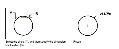
To create a diametral dimension
Do one of the following to choose Diameter:
- On the ribbon, choose Annotate > Diameter (in Dimensions).
- On the menu, choose Dimensions > Diameter.
- On the Dimensioning toolbar, click the Diameter tool.
- Type dimdiameter and then press Enter.
Select the arc or circle.
Specify the dimension line location.
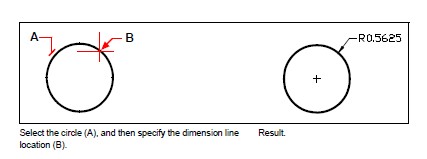
To create a radial dimension
Do one of the following to choose Radius:
- On the ribbon, choose Annotate > Radius (in Dimensions).
- On the menu, choose Dimensions > Radius.
- On the Dimensioning toolbar, click the Radius tool.
- Type dimradius and then press Enter.
Select the arc or circle.
Specify the dimension line location.
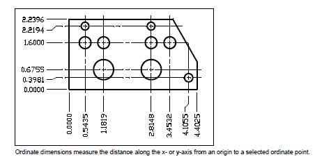
Creating ordinate dimensions
An ordinate dimension annotates the perpendicular distance from an origin or base point (the origin of the current user coordinate system [UCS]). Ordinate dimensions consist of an x- or y-coordinate and a leader. An
x-ordinate dimension measures distances along the x-axis; a y-ordinate dimension measures distances along the y-axis.
As you select ordinate points, the program automatically determines whether the point is an x- or y-ordinate based on which direction you drag the second point. You can also specify whether the ordinate represents an x- or y-ordinate. Ordinate dimension text is always aligned with the ordinate leader lines, regardless of the text orientation specified by the current dimension style.
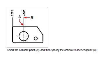
To create an ordinate dimension
Do one of the following to choose Ordinate:
- On the ribbon, choose Annotate > Ordinate (in Dimensions).
- On the menu, choose Dimensions > Ordinate.
- On the Dimensioning toolbar, click the Ordinate tool.
- Type dimordinate and then press Enter.
Select the point for ordinate dimension.
Specify the ordinate leader endpoint.
Selecting exact points is important when creating dimensions.
Use entity snaps to select precise ordinate points.
Creating leaders and annotations
Leaders consist of a line or series of lines that connects a feature in a drawing to an annotation. Generally, you place an arrowhead at the first point. An annotation, created as dimension text, is placed immediately adjacent to the last point. By default, the text placed at the end of the leader line consists of the most recent dimension. You can also type an annotation as a single line of text.
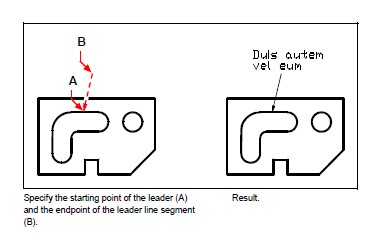
To create a leader and an annotation
Do one of the following to choose Leader:
- On the ribbon, choose Annotate > Leader (in Dimensions).
- On the menu, choose Dimensions > Leader.
- On the Dimensioning toolbar, click the Leader tool.
- Type dimleader and then press Enter.
Specify the starting point of the leader.
Specify the endpoint of the leader line segment.
Specify additional leader line segment endpoints.
After you specify the last endpoint, press Enter.
Type the annotation, or press Enter to accept the most recent dimension as the default annotation.
Dimensioning model space entities in paper space
To increase efficiency, you can separate your drawing model from annotations using the Model and Layout tabs.
It takes time to display dimensions, title blocks, keynotes, and other annotations. If you draw these on a Layout tab, display-time and visual clutter are reduced when you work on your model (on the Model tab). CADdirect 2022 allows you to dimension model space entities on either the Model tab or a Layout tab — you can make the choice depending on the method that works best for your needs.
To dimension model space entities in paper space
Click a Layout tab.
Create at least one layout viewport. For details, see “Creating layout viewports” on page 457.
Lock the desired layout viewport by doing the following:
- Right-click the edge of the layout viewport that you want to use for creating dimensions.
- Choose Properties.
- Mark Lock Viewport, and then click OK.
Locking the viewport is not required, but it is extremely helpful when you zoom or pan in the layout viewport; it prevents the viewport scale and view center from changing.
You can work in a layout viewport without having it clutter your display or selections.
Place layout viewports on their own layer, and after locking the layout viewports, hide the layer that contains them.
Make sure you are working in paper space by verifying that the Model/Paper Space toggle in the status bar begins with “P.” If necessary, switch to paper space by double-clicking the Model/Paper Space toggle in the status bar.
Create a dimension. You can select the model space entities directly, specify definition points, or use entities snaps to help accurately select the definition points.
The dimension is created in paper space.
For more details about using paper space and model space, see “Understanding paper space and model space” on page 450.
© Copyright 2021 BackToCAD Technolgies LLC . All rights reserved. Kazmierczak® is a registered trademark of Kazmierczak Software GmbH. CADdirect 2022 is a trademark of Expert Robotics Inc. Print2CAD and CAD2Print are Trademarks of BackToCAD Technologies LLC. DWG is the name of Autodesk’s proprietary file format and technology used in AutoCAD® software and related products. Autodesk, the Autodesk logo, AutoCAD, DWG are registered trademarks or trademarks of Autodesk, Inc., and/or its subsidiaries and/or affiliates in the USA and/or other countries. All other brand names, product names, or trademarks belong to their respective holders. This website is independent of Autodesk, Inc., and is not authorized by, endorsed by, sponsored by, affiliated with, or otherwise approved by Autodesk, Inc. The material and software have been placed on this Internet site under the authority of the copyright owner for the sole purpose of viewing of the materials by users of this site. Users, press, or journalists are not authorized to reproduce any of the materials in any form or by any means, electronic or mechanical, including data storage and retrieval systems, recording, printing or photocopying.