BackToCAD Technologies LLC | Artificial Intelligence and Software Developing | Clearwater, USA; Stuttgart, Germany | Kazmierczak® Company
Creating three-dimensional entities
CADdirect 2022 supports the following types of three-dimensional models:
- Wire-frame models, which consist of lines and curves that define the edges of a three-dimensional entity. You can create a wire-frame model by drawing lines, arcs, polylines, and other two-dimensional entities anywhere in three-dimensional space. Wire-frame models have no surfaces; they always appear as outlines. Because you must individually draw and position each entity that makes up a wire-frame model, creating one can be exacting and time-consuming.
- Surface models, which consist of both edges and the surfaces between those edges. You can create a surface model by applying elevation and thickness to two-dimensional planar entities or by using specific three-dimensional entity-creation commands. Surface models consist of individual planes forming a faceted, polygonal mesh.
- 3D solids, which are three-dimensional ACIS entities that consist of faces and edges. 3D solids appear to have volume and are easier to work with than wire-frame and surface models. CADdirect 2022 supports viewing and limited editing of 3D solids, including moving, rotating and scaling. Additionally, some versions of CADdirect 2022 allow you to create and more completely edit 3D solids.
Applying elevation and thickness
By default, the program creates new two-dimensional entities with a zero elevation and thickness. The easiest way to create a three-dimensional entity is to change the elevation or thickness property of an existing two-dimensional entity.
The elevation of an entity is its z-coordinate position in relation to the xy plane in which the entity is drawn. An elevation of 0 indicates that the entity is drawn on the xy plane of the current UCS. Positive elevations are above this plane; negative elevations are below it.
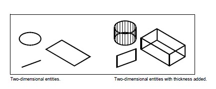
The thickness of an entity is the distance it is extruded above or below its elevation. A positive thickness extrudes the entity upward in the positive z direction of the entity; a negative thickness extrudes it downward in the negative z direction. The thickness is applied uniformly to the entire entity. You can extrude any two-dimensional entity into a three-dimensional entity by changing the thickness of the entity to a nonzero value. For example, a circle becomes a cylinder, a line becomes a three-dimensional plane, and a rectangle becomes a box.
You can create three-dimensional entities using any of the following methods:
- Draw two-dimensional entities in three-dimensional space.
- Convert two-dimensional planar entities into three-dimensional entities by applying elevation and thickness.
- Convert two-dimensional planar entities into three-dimensional entities by revolving or extruding.
- Create three-dimensional entities such as boxes, cylinders, cones, domes, spheres, and wedges.
Three-dimensional solids are drawn as true solids with versions of CADdirect 2022 that support three-dimensional ACIS solids.
Three-dimensional solids that you can create include: box, cone, cylinder, dish, dome, pyramid, sphere, torus, and wedge.
You can change the default elevation and thickness values to create new entities with an elevation and thickness already applied.
To set the current elevation
Do one of the following to choose Elevation:
- On the ribbon, choose Draw > Elevation (in Settings).
- On the menu, choose Format > Elevation.
- On the Format toolbar, click the Elevation tool.
- Type elev and then press Enter.
Specify the New Current Value For Elevation, and then press Enter.
To set the current thickness
Do one of the following to choose Thickness:
- On the ribbon, choose Draw > Thickness (in Settings).
- On the menu, choose Format > Thickness.
- On the Format toolbar, click the Thickness tool.
- Type thickness and then press Enter.
Specify the New Current Value For Thickness, and then press Enter.
To set the current elevation and thickness using a dialog box
Do one of the following to choose Drawing Settings:
- On the ribbon, choose Home > Drawing Settings (in Utilities) or choose Tools > Drawing Settings (in Manage).
- On the menu, choose Tools > Drawing Settings.
- On the Tools toolbar, click the Drawing Settings tool.
- Type settings and then press Enter.
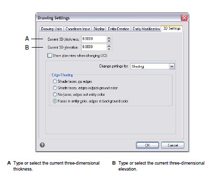
Click the 3D Settings tab.
In the Change Settings For list, click Surfaces.
To change the current thickness, in the Current 3D Thickness box, type a new thickness value or click the arrows to select a new thickness.
To change the current elevation, in the Current 3D Elevation box, type a new elevation value or click the arrows to select a new elevation.
Click OK.
To change the thickness and elevation of an existing entity
Do one of the following to choose Properties:
- On the ribbon, choose the Application button then choose Options, or choose Tools > Options (in Manage).
- On the menu, choose Modify > Properties.
- On the Modify toolbar, click the Properties tool.
- Type entprop and then press Enter.
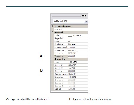
Select the entity, and then press Enter. CADdirect 2022 displays the Properties palette (its exact appearance depends on the type of entity you select).
To change the thickness, in the Thickness box, type a new thickness value or click the arrows to select the new thickness.
To change the elevation, in the Z coordinate box (or some entities have an Elevation box), type a new elevation value or click the arrows to select the new elevation.
Click OK.
When you change the thickness of an entity, you do not change the entity type.
If you want to extrude an entity and convert it to a three-dimensional solid, use the Extrude command.
Creating three-dimensional faces
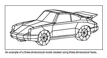
You can create a three-dimensional face, which consists of a section of a plane in three-dimensional space. You define a three-dimensional face by specifying the x,y,z coordinates of three or more corners. After you specify the fourth point, the program continues to prompt you for additional faces by alternating prompts for the third point and fourth point to allow you to build a complex three-dimensional entity. Each three- or four-sided plane is created as a separate three-dimensional face entity.
To create a three-dimensional face
Advanced experience level
Do one of the following to choose Face:
- On the ribbon, choose Draw 3D > 3D Face (in Draw 3D Meshes).
- On the menu, choose Draw > 3D Meshes > Face.
- On the Draw 3D Meshes toolbar, click the Face tool.
- Type face and then press Enter.
Specify the first point of the three-dimensional face.
Specify the second, third, and fourth points.
Specify the third and fourth points for additional faces.
To complete the command, press Enter.
Any or all edges of a three-dimensional face can be invisible to allow you to more accurately model entities with holes in them.
As the program prompts you for the corner points, in the prompt box, choose Invisible Edge to make the next edge invisible.
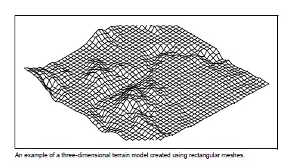
Creating rectangular meshes
You can create a three-dimensional rectangular mesh consisting of four-sided polygons. You determine the size of the mesh by specifying the number of vertices along the primary (M-direction) and secondary (N-direction) mesh axes and then specifying the coordinates for each vertex.
To create a rectangular mesh
Advanced experience level
Do one of the following to choose Mesh:
- On the ribbon, choose Draw 3D > Meshes (in Draw 3D Meshes).
- On the menu, choose Draw > 3D Meshes > Mesh.
- On the Draw 3D Meshes toolbar, click the Mesh tool.
- Type mesh and then press Enter.
Specify the number of vertices along the primary mesh axis.
Specify the number of vertices along the secondary mesh axis.
Specify the coordinates for each vertex.
Specifying the coordinates for the last vertex completes the mesh and ends the command.
Although creating rectangular meshes manually can be exacting, they are useful for representing complex surfaces such as three-dimensional terrain models.
The Mesh tool is most useful when combined with scripts or LISP programs that mathematically calculate the coordinates of the vertices.
Creating polyface meshes
You can create a polygon mesh consisting of faces connecting three or more vertices. You first determine the coordinates of each vertex and then define each face by entering the vertex numbers for all the vertices of that face. As you create each face, you can control the visibility and color of each edge and assign each edge to specific layers.
To create a polyface mesh
Advanced experience level
Do one of the following to choose Polyface Mesh:
- On the ribbon, choose Draw 3D > Polyface Mesh (in Draw 3D Meshes).
- On the menu, choose Draw > 3D Meshes > Polyface Mesh.
- On the Draw 3D Meshes toolbar, click the Polyface Mesh tool.
- Type pface and then press Enter.
Specify the coordinates of each vertex.
After each vertex that you specify, the next vertex number is displayed, and you are prompted for the coordinates of the vertex. Specify the coordinates, and then press Enter. Continue to specify the coordinates for each numbered vertex.
To finish specifying vertex coordinates, press Enter.
Specify the vertex numbers that define the first face.
You specify the face by entering the vertex numbers that were defined when you specified coordinates in step 2. Each face can be composed of three or more numbered vertices.
To finish defining the first face, press Enter.
Specify the next face by entering its vertex numbers.
To complete the command, press Enter.
Edges can be made invisible.
Type the vertex number as a negative value.
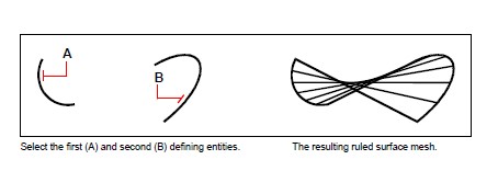
Creating ruled surface meshes
You can create a ruled surface, which is a three-dimensional polygon mesh that approximates the surface between two existing entities. You select the two entities that define the ruled surface. These entities can be arcs, circles, lines, points, or polylines.
To create a ruled surface mesh
Advanced experience level
Do one of the following to choose Ruled Surface:
- On the ribbon, choose Draw 3D > Ruled Surface (in Draw 3D Meshes).
- On the menu, choose Draw > 3D Meshes > Ruled Surface.
- On the Draw 3D Meshes toolbar, click the Ruled Surface tool.
- Type rulesurf and then press Enter.
Select the first defining entity.
Select the second defining entity.
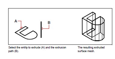
Creating extruded surface meshes
You can create an extruded surface, which is a three-dimensional polygon mesh that approximates the surface generated by extruding a path curve along a direction vector. You select the two entities that define the path curve and direction vector. The length of the direction vector determines the distance the path curve is moved along the direction vector. The extruded entity can be an arc, circle, line, or polyline. You can choose a line or open polyline as the direction vector. The resulting mesh consists of a series of parallel polygonal planes running along the specified path.
To create an extruded surface mesh
Advanced experience level
Do one of the following to choose Extruded Surface:
- On the ribbon, choose Draw 3D > Extruded Surface (in Draw 3D Meshes).
- On the menu, choose Draw > 3D Meshes > Extruded Surface.
- On the Draw 3D Meshes toolbar, click the Extruded Surface tool.
- Type tabsurf and then press Enter.
Select the entity to extrude.
Select the extrusion path.
The value of the Number of M-Direction Surfaces controls the density of the mesh. Choose Tools > Drawing Settings, and then click the 3D Settings tab. Under Change Settings For, select Surfaces. Under Surface Settings, change the Number Of M-Direction Surfaces. Or, on the Tools toolbar, use the Drawing Settings tool to display that dialog box.
An extruded mesh is different from an extruded solid, If you want to extrude an entity and convert it to a three-dimensional solid, use the Extrude command.
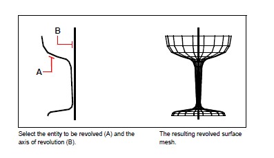
Creating revolved surface meshes
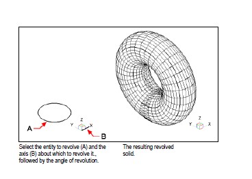
You can create a surface of revolution, which is a three-dimensional polygon mesh that approximates the surface generated by rotating a two-dimensional profile around an axis. You select the two entities that define the profile and the axis. You also specify the starting angle and the number of degrees to revolve the profile.
Revolving the profile 360 degrees creates a closed three-dimensional mesh. The Number Of M-Direction Surfaces value determines the mesh density (the number of mesh segments) in the M-direction (around the axis of revolution). The N-Direction Mesh Density value determines the mesh density (the number of mesh segments) in the N-direction (along the axis of revolution).
To create a revolved surface mesh
Advanced experience level
Do one of the following to choose Revolved Surface:
- On the ribbon, choose Draw 3D > Revolved Surface (in Draw 3D Meshes).
- On the menu, choose Draw > 3D Meshes > Revolved Surface.
- On the Draw 3D Meshes toolbar, click the Revolved Surface tool.
- Type revsurf and then press Enter.
Select the entity to revolve.
Select the entity to be used as the axis of revolution.
Specify the starting angle.
Specify the number of degrees to revolve the entity.
The values of the Number of M-Direction Surfaces and N-Direction Mesh Density control the density of the mesh.
Choose Tools > Drawing Settings, and then click the 3D Settings tab. Under Change Settings For, select Surfaces. Under Surface Settings, change the Number Of M-Direction Surfaces and N-Direction Mesh Density values. Or on the Tools toolbar, use the Drawing Settings tool to display that dialog box.
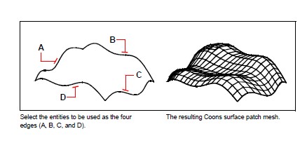
Creating edge-defined Coons surface patch meshes
You can create a surface called a Coons surface patch, a mesh connecting four edges. You select the entities that define the edges. Edge entities can be arcs, lines, or polylines. The four edge entities must form a closed loop and share endpoints. A patch is a bicubic surface (one curve extends in the M-direction and the other in the N-direction) interpolated between the four adjoining edges. You can select the edges in any order. The first edge you select determines the M-direction of the mesh.
To create an edge-defined Coons surface patch mesh
Advanced experience level
Do one of the following to choose Coons Surface:
- On the ribbon, choose Draw 3D > Coons Surface (in Draw 3D Meshes).
- On the menu, choose Draw > 3D Meshes > Coons Surface.
- On the Draw 3D Meshes toolbar, click the Coons Surface tool.
- Type edgesurf and then press Enter.
Select the first edge.
Select the second, third, and fourth edges.
The values of the Number of M-Direction Surfaces and N-Direction Mesh Density control the density of the mesh.
Choose Tools > Drawing Settings, and then click the 3D Settings tab. Under Change Settings For, select Surfaces. Under Surface Settings, change the Number Of M-Direction Surfaces and N-Direction Mesh Density values. Or on the Tools toolbar, use the Drawing Settings tool to display that dialog box.
Creating boxes
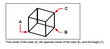
You can create rectangular boxes, or cubes. A box consists of six rectangular surface planes. The base of the box is always parallel with the xy plane of the current UCS. You position the box by specifying either a corner or the center of the box. You deter-mine the size of the box by either specifying a second corner and the height; defining the box to be a cube and then providing its length; or specifying the length, width, and height.
To create a box as an ACIS solid
Do one of the following to choose Box:
- On the ribbon, choose Draw 3D > Box (in Draw 3D Solids).
- On the menu, choose Draw > 3D Meshes > Box.
- On the Draw 3D Solids toolbar, click the Box tool.
- Type box and then press Enter.
Specify the first corner of the base.
Specify the opposite corner of the base.
Specify the height.
To create a box as a 3D mesh
Do one of the following to choose Box:
- On the ribbon, choose Draw 3D > Box (in Draw 3D Meshes).
- On the menu, choose Draw > 3D Meshes > Box.
- On the Draw 3D Meshes toolbar, click the Box tool.
- Type ai_box and then press enter.
Specify the first corner of the base.
Specify the opposite corner of the base.
Specify the height.
Creating wedges
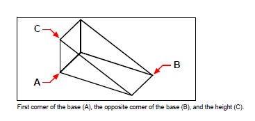
You can create three-dimensional wedges consisting of five surface planes. The base of the wedge is always parallel with the xy plane of the current UCS with the sloped face opposite the first corner. The height is always parallel with the z-axis. You position the wedge by specifying either a corner or the center of the wedge. You deter-mine the size of the wedge by either specifying a second corner and the height; defining the wedge based on a cube having a given length; or specifying the length, width, and height.
To create a wedge as an ACIS solid
Do one of the following to choose Wedge:
- On the ribbon, choose Draw 3D > Wedge (in Draw 3D Solids).
- On the menu, choose Draw > 3D Meshes > Wedge.
- On the Draw 3D Solids toolbar, click the Wedge tool.
- Type wedge and then press Enter.
Specify the first corner of the base.
Specify the opposite corner of the base.
Specify the height.
To create a wedge as a 3D mesh
Do one of the following to choose Wedge:
- On the ribbon, choose Draw 3D > Wedge (in Draw 3D Meshes).
- On the menu, choose Draw > 3D Meshes > Wedge.
- On the Draw 3D Meshes toolbar, click the Wedge tool.
- Type ai_wedge and then press Enter.
Specify the first corner of the base.
Specify the opposite corner of the base.
Specify the height.
Creating cones
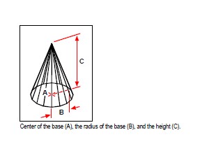
You can create three-dimensional cones defined by a circular base and tapering to a point perpendicular to the base. The base of the cone is always parallel with the xy plane of the current UCS; the height of the cone is always parallel with the z-axis. You position the cone by specifying the center of the base. You determine the size of the cone by specifying either the radius or the diameter of the base and the height.
To create a cone as an ACIS solid
Do one of the following to choose Cone:
- On the ribbon, choose Draw 3D > Cone (in Draw 3D Solids).
- On the menu, choose Draw > 3D Meshes > Cone.
- On the Draw 3D Solids toolbar, click the Cone tool.
- Type cone and then press Enter.
Specify the center of the base of the cone.
Specify the radius or diameter.
Specify the height.
To create a cone as a 3D mesh
Do one of the following to choose Cone:
- On the ribbon, choose Draw 3D > Cone (in Draw 3D Meshes).
- On the menu, choose Draw > 3D Meshes > Cone.
- On the Draw 3D Meshes toolbar, click the Cone tool.
- Type ai_cone and then press Enter.
Specify the center of the base of the cone.
Specify the radius or diameter.
Specify the height.
Creating pyramids
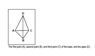
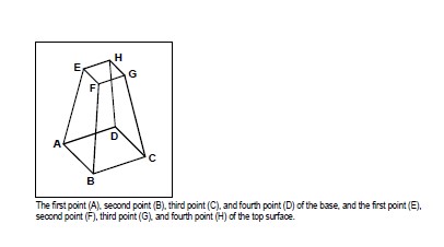
You can create tetrahedrons (three-sided pyramids) or four-sided pyramids. The sides of the resulting pyramid can meet at a point (the apex) or can form a three- or four-edged top. The sides of a four-sided pyramid can also meet along a ridge defined by two points. The base of the pyramid is always parallel with the xy plane of the current UCS. You position the pyramid by specifying a corner of the base. You determine the size of the pyramid by specifying the base points and either the apex, the corners of the top surface, or the endpoints of the ridge.
To create a tetrahedron as an ACIS solid
Do one of the following to choose Pyramid:
- On the ribbon, choose Draw 3D > Pyramid (in Draw 3D Solids).
- On the menu, choose Draw > 3D Meshes > Pyramid.
- On the Draw 3D Solids toolbar, click the Pyramid tool.
- Type pyramid and then press Enter.
Specify the first point for the base of the pyramid.
Specify the second and third points.
In the prompt box, choose Tetrahedron.
Specify the apex of the tetrahedron.
To create a tetrahedron as a 3D mesh
Do one of the following to choose Pyramid:
- On the ribbon, choose Draw 3D > Pyramid (in Draw 3D Meshes).
- On the menu, choose Draw > 3D Meshes > Pyramid.
- On the Draw 3D Meshes toolbar, click the Pyramid tool.
- Type ai_pyramid and then press Enter.
Specify the first point for the base of the pyramid.
Specify the second and third points.
In the prompt box, choose Tetrahedron.
Specify the apex of the tetrahedron.
To create a pyramid with a planar top as an ACIS solid
Do one of the following to choose Pyramid:
- On the ribbon, choose Draw 3D > Pyramid (in Draw 3D Solids).
- On the menu, choose Draw > 3D Meshes > Pyramid.
- On the Draw 3D Solids toolbar, click the Pyramid tool.
- Type pyramid and then press Enter.
Specify the first point for the base of the pyramid.
Specify the second, third, and fourth points.
In the prompt box, choose Top Surface.
Specify the first point on the top surface of the pyramid.
Specify the second, third, and fourth points.
To create a pyramid with a planar top as a 3D mesh
Do one of the following to choose Pyramid:
- On the ribbon, choose Draw 3D > Pyramid (in Draw 3D Meshes).
- On the menu, choose Draw > 3D Meshes > Pyramid.
- On the Draw 3D Meshes toolbar, click the Pyramid tool.
- Type ai_pyramid and then press Enter.
Specify the first point for the base of the pyramid.
Specify the second, third, and fourth points.
In the prompt box, choose Top Surface.
Specify the first point on the top surface of the pyramid.
Specify the second, third, and fourth points.
Creating cylinders
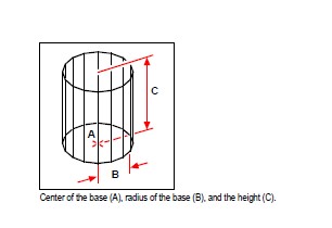
You can create cylinders defined by a circular base. The base of a cylinder is always parallel with the xy plane of the current UCS; the height of a cylinder is always parallel with the z-axis. You position a cylinder by specifying the center of the base. You determine the size of a cylinder by specifying either the radius or diameter of the base and the height.
To create a cylinder as an ACIS solid
Do one of the following to choose Cylinder:
- On the ribbon, choose Draw 3D > Cylinder (in Draw 3D Solids).
- On the menu, choose Draw > 3D Meshes > Cylinder.
- On the Draw 3D Solids toolbar, click the Cylinder tool.
- Type cylinder and then press Enter.
Specify the center of the base of the cylinder.
Specify the radius or diameter.
Specify the height.
To create a cylinder as a 3D mesh
Do one of the following to choose Cylinder:
- On the ribbon, choose Draw 3D > Cylinder (in Draw 3D Meshes).
- On the menu, choose Draw > 3D Meshes > Cylinder.
- On the Draw 3D Meshes toolbar, click the Cylinder tool.
- Type ai_cylinder and then press Enter.
Specify the center of the base of the cylinder.
Specify the radius or diameter.
Specify the height.
Creating spheres
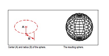
You can create spheres. The latitude lines of a sphere are always parallel with the xy plane of the current UCS; the central axis is always parallel with the z-axis. You position a sphere by specifying its center point. You determine the size of a sphere by specifying either its radius or its diameter.
To create a sphere as an ACIS solid
Do one of the following to choose Sphere:
- On the ribbon, choose Draw 3D > Sphere (in Draw 3D Solids).
- On the menu, choose Draw > 3D Meshes > Sphere.
- On the Draw 3D Solids toolbar, click the Sphere tool.
- Type sphere and then press Enter.
Specify the center of the sphere.
Specify the radius or diameter.
To create a sphere as a 3D mesh
Do one of the following to choose Sphere:
- On the ribbon, choose Draw 3D > Sphere (in Draw 3D Meshes).
- On the menu, choose Draw > 3D Meshes > Sphere.
- On the Draw 3D Meshes toolbar, click the Sphere tool.
- Type ai_sphere and then press Enter.
Specify the center of the sphere.
Specify the radius or diameter.
Specify the number of longitudinal sections that are perpendicular to the xy plane.
Specify the number of latitudinal sections that are parallel to the xy plane.
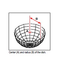
Creating dishes
You can create a three-dimensional dish. The latitude lines of a dish are always parallel with the xy plane of the current UCS; the central axis is always parallel with the z-axis. You position a dish by specifying its center point. You determine the size of a dish by specifying either its radius or its diameter.
To create a dish as an ACIS solid
Do one of the following to choose Dish:
- On the ribbon, choose Draw 3D > Dish (in Draw 3D Solids).
- On the menu, choose Draw > 3D Meshes > Dish.
- On the Draw 3D Solids toolbar, click the Dish tool.
- Type dish and then press Enter.
Specify the center of the dish.
Specify the radius or diameter.
To create a dish as a 3D mesh
Do one of the following to choose Dish:
- On the ribbon, choose Draw 3D > Dish (in Draw 3D Meshes).
- On the menu, choose Draw > 3D Meshes > Dish.
- On the Draw 3D Meshes toolbar, click the Dish tool.
- Type ai_dish and then press Enter.
Specify the center of the dish.
Specify the radius or diameter.
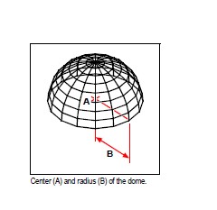
Creating domes
You can create a three-dimensional dome. The latitude lines of a dome are always parallel with the xy plane of the current UCS; the central axis is always parallel with the z-axis. You position a dome by specifying its center point. You determine the size of a dome by specifying either its radius or its diameter.
To create a dome as an ACIS solid
Do one of the following to choose Dome:
- On the ribbon, choose Draw 3D > Dome (in Draw 3D Solids).
- On the menu, choose Draw > 3D Meshes > Dome.
- On the Draw 3D Solids toolbar, click the Dome tool.
- Type dome and then press Enter.
Specify the center of the dome.
Specify the radius or diameter.
To create a dome as a 3D mesh
Do one of the following to choose Dome:
- On the ribbon, choose Draw 3D > Dome (in Draw 3D Meshes).
- On the menu, choose Draw > 3D Meshes > Dome.
- On the Draw 3D Meshes toolbar, click the Dome tool.
- Type ai_dome and then press Enter.
Specify the center of the dome.
Specify the radius or diameter.
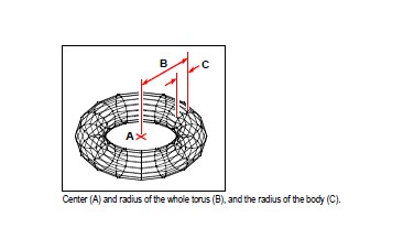
Creating tori
You can create a three-dimensional donut or ring-shaped entity known as a torus. The diameter of a ring is always parallel with the xy plane of the current UCS. A torus is constructed by revolving a circle about a line drawn in the plane of the circle and parallel with the z-axis of the current UCS. You position a torus by specifying its center point. You determine the size of a torus by specifying its overall diameter or radius and the diameter or radius of the tube (the circle being revolved).
To create a torus as an ACIS solid
Do one of the following to choose Torus:
- On the ribbon, choose Draw 3D > Torus (in Draw 3D Solids).
- On the menu, choose Draw > 3D Meshes > Torus.
- On the Draw 3D Solids toolbar, click the Torus tool.
- Type torus and then press Enter.
Specify the center of the whole torus.
Specify the radius or diameter of the whole torus.
Specify the radius or diameter of the body of the torus.
To create a torus as a 3D mesh
Do one of the following to choose Torus:
- On the ribbon, choose Draw 3D > Torus (in Draw 3D Meshes).
- On the menu, choose Draw > 3D Meshes > Torus.
- On the Draw 3D Meshes toolbar, click the Torus tool.
- Type ai_torus and then press Enter.
Specify the center of the whole torus.
Specify the radius or diameter of the whole torus.
Specify the radius or diameter of the body of the torus.
Specify the number of longitudinal sections that are perpendicular to the xy plane.
Specify the number of latitudinal sections that are parallel to the xy plane.
Creating regions
You can convert a closed entity into a two-dimensional region. After you create a region, you can modify it using the various three-dimensional tools. For example, you can create a region from a square, and then extrude the square to create a three-dimensional cube.
You can create regions from closed entities, such as polylines, polygons, circles, ellipses, closed splines, and donuts.
Creating regions typically has no visible effect on a drawing. However, if the original entity had a width or lineweight, that information is lost when you create the region.
To create a region
Do one of the following to choose Region:
- On the ribbon, choose Draw 3D > Region (in Draw 3D Solids).
- On the menu, choose Draw > 3D Solids > Region.
- On the Draw 3D Solids toolbar, click the Region tool.
- Type region and then press Enter.
Select the entities to create the region.
Press Enter.
The command bar displays a message that describes how many regions were created.
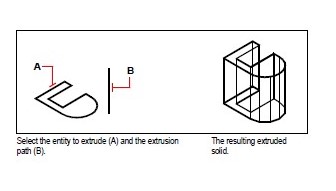
Creating extruded solids
You can create three-dimensional solids by extruding closed entities, such as polylines, polygons, circles, ellipses, closed splines, donuts, and regions.
You can extrude the entity along a selected path, or you can specify its height and taper angle.
To create an extruded solid
Do one of the following to choose Extrude:
- On the ribbon, choose Draw 3D > Extrude (in Draw 3D Solids).
- On the menu, choose Draw > 3D Solids > Extrude.
- On the Draw 3D Solids toolbar, click the Extrude tool.
- Type extrude and then press Enter.
Select the entity to extrude.
Select the extrusion path, or specify the height.
Creating revolved solids (Pro Version Only)
You can create three-dimensional solids by revolving closed entities, such as polylines, polygons, circles, ellipses, and regions. You can revolve the entity about a defined axis, line, polyline, or two points.
To create a revolved solid (Pro Version Only)
Do one of the following to choose Revolve:
- On the ribbon, choose Draw 3D > Revolve (in Draw 3D Solids).
- On the menu, choose Draw > 3D Solids > Revolve.
- On the Draw 3D Solids toolbar, click the Revolve tool.
- Type revolve and then press Enter.
Select the entity to revolve.
Do one of the following to define the axis of revolution:
- Specify a start point and an end point.
- Type o and press Enter to select an entity that determines the axis.
- Type x and press Enter to select the x-axis.
- Type y and press Enter to select the y-axis.
Specify the angle of revolution.
Creating lofted solids and surfaces (Pro Version Only)
Creates a three-dimensional solid or surface between two or more cross sections. Cross sections can be open or closed entities. Open cross sections create three-dimensional surfaces. Closed cross sections create three-dimensional solids or surfaces, depending on the specified mode.
Cross sections can be 2D polylines, lines, arcs, circles, ellipses, elliptical arcs, 2D splines, helices, traces, edges of entities, faces of a solid or surface, points of the first or last cross section, regions, and 2D solids.
Guides can be 2D polylines with a single segment, 3D polylines, lines, arcs, elliptical arcs, 2D and 3D splines, and edges of entities.
Paths can be 2D and 3D polylines, lines, arcs, circles, ellipses, elliptical arcs, 2D and 3D splines, helices, and edges of entities.
To create a lofted solid or surface (Pro Version Only)
Do one of the following to choose Loft:
- On the ribbon, choose Draw 3D > Loft (in Draw 3D Solids).
- On the menu, choose Draw > 3D Solids > Loft.
- On the Draw 3D Solids toolbar, click the Loft tool.
- Type loft and then press Enter.
Select the cross sections in the order you want them to loft. You must select at least two cross sections.
If desired, choose Point to taper the loft entity. Select the taper point on a cross section, then press Enter.
If desired, choose Join multiple edges to create a cross section from edges. Select the edges, which must share start and end points, to be considered as a cross section. When done selecting edges, press Enter.
If needed, choose Mode to change whether a three-dimensional solid or surface is created, then press enter.
Press Enter to continue.
Choose one of the following:
- Guides —Creates the loft entity using guide curves which help shape the entity. Select the guide curves for the loft entity. Guide curves must intersect each cross section and begin and end at the first and last cross section. You can also combine multiple edges to form a guide.
- Path — Creates the loft entity along a path. Select the path for the lofted entity. The path must intersect the solid or surface on all planes.
- Cross sections only — Creates the loft entity between the cross sections without using guides or paths.
- Settings — Opens the Loft Settings dialog box to specify various settings.
Creating swept solids and surfaces
You can create three-dimensional solids or surfaces by sweeping an entity along a path.
Entities that you can sweep include 2D polylines, lines, arcs, circles, ellipses, elliptical arcs, 2D and 3D splines, 3D solid faces, and 2D solids.
Entities that can be the path include 2D and 3D polylines, lines, arcs, circles, ellipses, elliptical arcs, 2D and 3D splines, helices, and edges of solids, surfaces, or meshes.
To create a swept solid or surface
Do one of the following to choose Sweep:
- On the ribbon, choose Draw 3D > Sweep (in Draw 3D Solids).
- On the menu, choose Draw > 3D Solids > Sweep.
- On the Draw 3D Solids toolbar, click the Sweep tool.
- Type sweep and then press Enter.
Select one or more entities to sweep.
You can choose Mode to change whether a three-dimensional solid or surface is created.
Select the path.
If desired, choose any of the following options:
- Alignment — Aligns the sweep entity to be perpendicular (normal) to the tangent direction of the sweep path.
- Base point — Determines the base point of the sweep entity.
- Scale — Determines the scale factor for the sweep entity. If there are multiple sweep entities, the scale factor is applied to each entity. You can also choose Reference to select reference points in the drawing for scaling.
- Twist — Determines the degrees in which to rotate the sweep entity along the path. If there are multiple sweep entities, the twist angle is applied to each entity. You can also choose Bank to determine whether the sweep entity being swept rotates along a 3D path such as a 3D polyline, spline, or helix.
Creating polysolids (Pro Version Only)
You can create three-dimensional solids with a rectangular profile from a new polyline that you draw or from an existing line, arc, polyline, or circle.
To create a polysolid without converting any entities (Pro Version Only)
Do one of the following to choose Polysolid:
- On the ribbon, choose Draw 3D > Polysolid (in Draw 3D Solids).
- On the menu, choose Draw > 3D Solids > Polysolid.
- On the Draw 3D Solids toolbar, click the Polysolid tool.
- Type polysolid and then press Enter.
Select the start point of the polysolid.
Continue selecting points. You can choose Arc to create an arc segment. You can also choose Undo to erase the previous point.
Choose Height and specify the height of the polysolid. The default height is specified by the PSOLHEIGHT system variable.
Choose width and specify the width of the polysolid. The default height is specified by the PSOLWIDTH system variable.
Choose Justify to specify whether the width and height should be justified to the left, center, or right. Justification orientation is determined according to the direction of the first profile segment.
To create a polysolid from an existing entity (Pro Version Only)
Do one of the following to choose Polysolid:
- On the ribbon, choose Draw 3D > Polysolid (in Draw 3D Solids).
- On the menu, choose Draw > 3D Solids > Polysolid.
- On the Draw 3D Solids toolbar, click the Polysolid tool.
- Type polysolid and then press Enter.
Choose Entity, then press Enter.
Select the entity you want to convert to a polysolid. You can select a line, arc, polyline, or circle.
Choose Height and specify the height of the polysolid. The default height is specified by the PSOLHEIGHT system variable.
Choose width and specify the width of the polysolid. The default height is specified by the PSOLWIDTH system variable.
Choose Justify to specify whether the width and height should be justified to the left, center, or right. Justification is determined according to the direction of the first profile segment.
Creating composite solids (Pro Version Only)
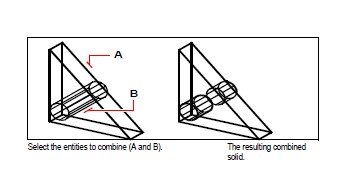
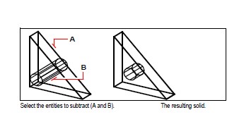
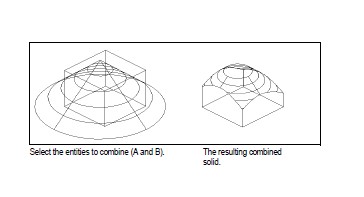
You can create composite three-dimensional solids by combining, subtracting, and finding the intersection of two or more solids.
To combine solids
Do one of the following to choose Union
- On the ribbon, choose Draw 3D > Union (in Solids Editing).
- On the menu, choose Modify > Solids Editing > Union.
- On the Solids Editing toolbar, click the Union tool.
- Type union and then press Enter.
Select the entities to combine.
To subtract solids (Pro Version Only)
Do one of the following to choose Subtract:
- On the ribbon, choose Draw 3D > Subtract (in Solids Editing).
- On the menu, choose Modify > Solids Editing > Subtract.
- On the Solids Editing toolbar, click the Subtract tool.
- Type subtract and then press Enter.
Select the entities to subtract from one another.
To intersect solids (Pro Version Only)
Do one of the following to choose Intersect:
- On the ribbon, choose Draw 3D > Intersect (in Solids Editing).
- On the menu, choose Modify > Solids Editing > Intersect.
- On the Solids Editing toolbar, click the Intersect tool.
- Type intersect and then press Enter.
Select the entities to intersect.
© Copyright 2021 BackToCAD Technolgies LLC . All rights reserved. Kazmierczak® is a registered trademark of Kazmierczak Software GmbH. CADdirect 2022 is a trademark of Expert Robotics Inc. Print2CAD and CAD2Print are Trademarks of BackToCAD Technologies LLC. DWG is the name of Autodesk’s proprietary file format and technology used in AutoCAD® software and related products. Autodesk, the Autodesk logo, AutoCAD, DWG are registered trademarks or trademarks of Autodesk, Inc., and/or its subsidiaries and/or affiliates in the USA and/or other countries. All other brand names, product names, or trademarks belong to their respective holders. This website is independent of Autodesk, Inc., and is not authorized by, endorsed by, sponsored by, affiliated with, or otherwise approved by Autodesk, Inc. The material and software have been placed on this Internet site under the authority of the copyright owner for the sole purpose of viewing of the materials by users of this site. Users, press, or journalists are not authorized to reproduce any of the materials in any form or by any means, electronic or mechanical, including data storage and retrieval systems, recording, printing or photocopying.