BackToCAD Technologies LLC | Artificial Intelligence and Software Developing | Clearwater, USA; Stuttgart, Germany | Kazmierczak® Company
Customizing and reusing print settings
Most drawings require adjustments to print settings in order to print the way you want. You can make adjustments to the print settings each time you print, but you can also create page setups, which save the print settings and assign them to different lay-outs in your drawing. If you have several perspectives of your drawing that require printing, using page setups is the most efficient way to print.
Working with page setups
Page setups store printer information for specific models or layouts, which eliminates the need to completely reconfigure your print settings each time you print a drawing and helps ensure that each perspective of a drawing prints as planned.
Assigning a page setup to a model or layout
Because the main model on the Model tab and the various layouts for printing on the Layout tabs all may require unique print settings, the model and each layout can be assigned a separate page setup. If some layouts use the same print settings, those layouts can be assigned the same page setup.
Assigning a page setup to a model or layout doesn’t mean it will always print with the specified settings. All of the print settings specified for a page setup can be overridden at print time.
To assign a page setup to a model or layout
Click the Model tab or Layout tab that you want to assign a page setup.
Do one of the following to choose Page Setup Manager:
- On the ribbon, choose the Application button then choose Page Setup Manager, or choose Output > Page Setup Manager (in Plot).
- On the menu, choose File > Page Setup Manager.
- On the Format toolbar, click the Page Setup Manager tool.
- Type pagesetup and then press Enter.
Select the desired page setup.
Click Set Current.
Click OK.
You can also choose a page setup at print time.
In the Print dialog box, select a different page setup from the Page Setup list before you click Print.
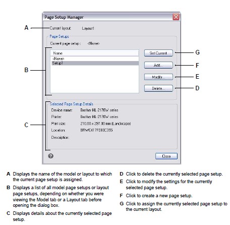
Creating a page setup
There are two types of page setups:
- Model page setup — Contains print settings available for the model on the Model tab.
- Layout page setup — Contains print settings available for one or more layouts on the Layout tabs.
CADdirect 2022 comes with two default page setups — one model page setup and one lay-out page setup. You can create as many additional page setups, of either type, as required for any drawing. Each page setup specifies many aspects of printing, including page size, default printer or plotter, page orientation, print scale, and more.
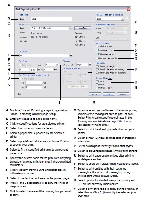
To create a page setup
To create a model page setup, click the Model tab. To create a layout page setup, click any Layout tab.
Do one of the following to choose Page Setup Manager:
- On the ribbon, choose the Application button then choose Page Setup Manager, or choose Output > Page Setup Manager (in Plot).
- On the menu, choose File > Page Setup Manager.
- On the Format toolbar, click the Page Setup Manager tool.
- Type pagesetup and then press Enter.
Click Add.
You can create a new page setup based on the print settings of an existing page setup.
Select an existing page setup in the list, then click Add. The new page setup uses the print settings of the existing page setup as a starting point.
Enter a name for the page setup, then click OK.
Select the desired print options.
Click OK.
Modifying an existing page setup
You can change any of the print settings associated with a page setup, which eliminates the need to override the settings when it comes time to print the model or each layout that is assigned the page setup.
If you change the settings for a layout print setup, all layouts assigned that print setup will print using the new settings.
To modify an existing page setup
To modify a model page setup, click the Model tab. To modify a layout page setup, click any Layout tab.
Do one of the following to choose Page Setup Manager:
- On the ribbon, choose the Application button then choose Page Setup Manager, or choose Output > Page Setup Manager (in Plot).
- On the menu, choose File > Page Setup Manager.
- On the Format toolbar, click the Page Setup Manager tool.
- Type pagesetup and then press Enter.
Select the page setup you want to change.
Click Modify.
Select the desired print options.
Click OK.
Deleting a page setup
If you delete a page setup that is assigned to the model or a layout, that model or lay-out will no longer be assigned a page setup.
To delete a page setup
To delete a model page setup, click the Model tab. To delete a layout page setup, click any Layout tab.
Do one of the following to choose Page Setup Manager:
- On the ribbon, choose the Application button then choose Page Setup Manager, or choose Output > Page Setup Manager (in Plot).
- On the menu, choose File > Page Setup Manager.
- On the Format toolbar, click the Page Setup Manager tool.
- Type pagesetup and then press Enter.
Select the page setup you want to delete.
Click Delete.
Click Yes to confirm the deletion.
Setting the paper size and orientation
You can specify a paper size and paper orientation for all drawings. You can also adjust the orientation by printing a drawing upside down on the paper. Each layout in your drawing can specify whether to print upside down.
To select the paper size and orientation
Click the Layout tab or Model tab for which you want to set paper size and orientation.
Do one of the following to choose Page Setup Manager:
- On the ribbon, choose the Application button then choose Page Setup Manager, or choose Output > Page Setup Manager (in Plot).
- On the menu, choose File > Page Setup Manager.
- On the Format toolbar, click the Page Setup Manager tool.
- Type pagesetup and then press Enter.
Select the desired page setup, then click Modify.
In Paper size, select a paper size supported by the currently selected printer.
In Orientation, select the following settings:
- Portrait or Landscape — Select Portrait for vertical paper orientation or Landscape for horizontal paper orientation.
- Print upside down — Select to print the drawing upside down on your printer.
Click OK.
Click OK.
Selecting a printer or plotter
You can specify a printer or plotter to be used when printing any drawing. You can print your drawing on any printer or plotter that is compatible with Windows, including raster printers.
To select a printer or plotter
Click the Layout tab or Model tab for which you want to select a printer.
Do one of the following to choose Page Setup Manager:
- On the ribbon, choose the Application button then choose Page Setup Manager, or choose Output > Page Setup Manager (in Plot).
- On the menu, choose File > Page Setup Manager.
- On the Format toolbar, click the Page Setup Manager tool.
- Type pagesetup and then press Enter.
Select the desired page setup, then click Modify.
From the Printer Name list, select a printer or plotter.
If desired, click Properties to choose options for the currently selected printer.
Click OK.
Click OK.
Setting the scale and view
You can print or plot the entire drawing or a selected portion of a drawing. You can choose to print what is visible on the screen, or you can specify to print an area of the drawing.
You can control the position of the drawing on the paper by specifying the origin of the print area, the location of the lower left corner of the print area, in relation to the lower left corner of the paper. The origin is normally set to 0,0, which places the lower left corner of the print area as close to the lower left corner of the paper as the printer or plotter will allow. You can specify a different origin, however, by specifying different coordinates.
When you create a drawing, you generally draw entities full-size. When you print the drawing, you can specify the scale of the resulting print or let the program adjust the size of the drawing to fit the paper. To print the drawing at a specific scale, specify the scale as a ratio of drawing units to printed units.
If you are printing from a Layout tab, the scale and view options you specify can be different for each layout that you create.
To automatically scale the drawing for printing
Click the Layout tab or Model tab for which you want to set to scale automatically.
Do one of the following to choose Page Setup Manager:
- On the ribbon, choose the Application button then choose Page Setup Manager, or choose Output > Page Setup Manager (in Plot).
- On the menu, choose File > Page Setup Manager.
- On the Format toolbar, click the Page Setup Manager tool.
- Type pagesetup and then press Enter.
Select the desired page setup, then click Modify.
In Print Scale, select Fit to Paper to scale the drawing to fit on one printed page.
Click OK.
Click OK.
To specify the scale factor yourself
Click the Layout tab or Model tab for which you want to specify the scale factor.
Do one of the following to choose Page Setup Manager:
- On the ribbon, choose the Application button then choose Page Setup Manager, or choose Output > Page Setup Manager (in Plot).
- On the menu, choose File > Page Setup Manager.
- On the Format toolbar, click the Page Setup Manager tool.
- Type pagesetup and then press Enter.
Select the desired page setup, then click Modify.
In Print Scale, do one of the following:
- Select a predefined scale in the Scale list. For example, choose 1:2 if you want 1 printed unit (inch or millimeter) to equal 2 drawing units. The list of available scales is set up using the Scales List command. For more details, see “Customizing the scales list” on page 57.
- Type the ratio of printed units of measure (inches or millimeters) to drawing units.
To specify the printed units of measure, choose Inches or Millimeters.
Click OK.
Click OK.
To specify a portion of the drawing to print
Click the Layout tab or Model tab for which you want to specify the area to print.
Do one of the following to choose Page Setup Manager:
- On the ribbon, choose the Application button then choose Page Setup Manager, or choose Output > Page Setup Manager (in Plot).
- On the menu, choose File > Page Setup Manager.
- On the Format toolbar, click the Page Setup Manager tool.
- Type pagesetup and then press Enter.
Select the desired page setup, then click Modify.
In What to Print, click one of the following:
- Display — Prints the view on the screen.
- Extents — Prints the area that contains entities in the drawing.
- Limits — Prints to the limits defined for the drawing. (Available for model page setups only.)
- Layout — Prints to the edge of the layout. (Available for layout page setups only.)
- View — Prints the selected saved view. (Available for drawings that have saved views.)
- Window — Prints the portion of the drawing contained in the specified window, maintaining the aspect ratio of the windowed area to the drawing.
If you clicked Window, you must specify the window. Under Windowed Print Area, enter the diagonal x- and y-coordinates of the window, or select the area on the screen.
Click OK.
Click OK.
To specify the print area origin
Click the Layout tab or Model tab for which you want to setting paper size and orientation.
Do one of the following to choose Page Setup Manager:
- On the ribbon, choose the Application button then choose Page Setup Manager, or choose Output > Page Setup Manager (in Plot).
- On the menu, choose File > Page Setup Manager.
- On the Format toolbar, click the Page Setup Manager tool.
- Type pagesetup and then press Enter.
Select the desired page setup, then click Modify.
Under Print Offset, do one of the following:
- To center the specified print area on the printed page, select Center on Page.
- To specify an origin for the print area, type the x- and y-coordinates.
Click OK.
Click OK.
Specifying print options specifically for layouts
Each layout in your drawing can specify certain print settings that apply only to layouts: lineweight scaling, print style display, and paper space print options.
To set print options for only layouts
Click a Layout tab.
Do one of the following to choose Page Setup Manager:
- On the ribbon, choose the Application button then choose Page Setup Manager, or choose Output > Page Setup Manager (in Plot).
- On the menu, choose File > Page Setup Manager.
- On the Format toolbar, click the Page Setup Manager tool.
- Type pagesetup and then press Enter.
Select the desired page setup, then click Modify.
In the Layout Tab Options area, choose the desired print settings:
Scale lineweights — Select to print lineweights in proportion to the specified Print Scale settings; if not selected, lineweights print at their assigned size. Note that print styles can also affect how lineweights print.
Display print styles — Select to show print styles when viewing the layout.
Print paper space last — Select to print paper space entities after printing model-space entities. By default, paper space entities print first.
Hide paper space entities — Select to prevent paper space entities from printing.
Click OK.
Click OK.
Specifying shaded viewport print options
Each model page setup can specify how to print shaded viewports: as displayed, wire-frame, hidden, or rendered. Note that Quality and DPI are not currently implemented.
To set print options for shaded viewports
Click the Layout tab or Model tab for which you want to set shaded viewport settings.
Do one of the following to choose Page Setup Manager:
- On the ribbon, choose the Application button then choose Page Setup Manager, or choose Output > Page Setup Manager (in Plot).
- On the menu, choose File > Page Setup Manager.
- On the Format toolbar, click the Page Setup Manager tool.
- Type pagesetup and then press Enter.
Select the desired page setup, then click Modify.
In the Shaded Viewport Options area, choose the desired settings:
- Shade — Select how to print shaded viewports
- Quality — Select the resolution to use for the printed viewport. (Not currently implemented.)
- DPI — Enter the custom dots per inch to use for printing the viewport shading. Available only if Quality is set to Custom. (Not currently implemented.)
Click OK.
Click OK.
Specifying pen and line printing options
Each layout in your drawing can specify certain print settings that apply only to lay-outs: lineweight scaling, print style display, and paper space print options.
To set pen and line printing options
Click the Layout tab or Model tab for which you want to set pen and line printing options.
Do one of the following to choose Page Setup Manager:
- On the ribbon, choose the Application button then choose Page Setup Manager, or choose Output > Page Setup Manager (in Plot).
- On the menu, choose File > Page Setup Manager.
- On the Format toolbar, click the Page Setup Manager tool.
- Type pagesetup and then press Enter.
Select the desired page setup, then click Modify.
Choose the desired settings:
- Print style table — Select a print style table to apply during printing, or select None. If you select a print style table, you can click [...] to modify its settings.
- Print with entity lineweights — Select to print entities with their assigned lineweights. If you turn off lineweight printing, entities print with a default outline. This option is available if Print with Print Styles option is disabled.
- Print with print styles — Select to print according to the print style settings in the currently selected print style table. Entity lineweights are ignored.
Click OK.
Click OK.
Using printer configuration files
Printer configuration files store the printer information you use for specific drawings or layouts, which eliminates the need to completely reconfigure your print settings each time you print a drawing. Printer configuration files also allow you to share and reuse print settings between different drawings and layouts.
CADdirect 2022 supports the printer configuration files (PCP and PC3 files) used by Auto-CAD. This feature makes it possible to use existing PCP files saved in AutoCAD, as well as to save your CADdirect 2022 print configuration settings to a PC3 format.
You can convert an AutoCAD PC2 file to PCP format using the Device And Default selection feature in the AutoCAD Print dialog box.
To save printer settings in a PC3 file
Do one of the following to choose Options
- On the ribbon, choose the Application button then choose Options, or choose Tools > Options (in Manage).
- On the menu, choose Tools > Options.
- Type config and then press Enter.
Click the Printing tab.
Click Add or Configure Printers.
To add a PC3 file, click Add to create a new PC3 file. In the Add Printer Configuration File dialog box that opens, select the desired printer for the new PC3 file, click Continue, and select the options you want for the PC3 file. If you don’t select any custom options, a PC3 file will not be created.
To modify or delete a PC3 file, select the desired file in the list and click Modify or Delete.
Click OK.
To assign a PCP file
If necessary, click the desired Layout tab or the Model tab.
Do one of the following:
- Choose File > Print.
- On the Standard toolbar, click the Print tool.
- Type print and then press Enter.
In Name for the printer, select the printer configuration file from the list.
Using plotter drivers
To print your drawing, the program sends the output to any printer driver in up to 256 colors, but with no width specified. Initially, the printed output will have a uniform fine width that is the finest line that the plotter device can produce.
The driver then passes colored vectors to the printer, which creates color output on color printers and grayscale output on laser printers. (Color output that converts to grayscale on a laser printer usually is unacceptable by CAD users for final printing.)
With print style tables, you can map all colors to black and set all lineweights to a width you choose. You must use a value appropriate to your printing capabilities. With these features, you can meet most non-presentation print needs.
© Copyright 2021 BackToCAD Technolgies LLC . All rights reserved. Kazmierczak® is a registered trademark of Kazmierczak Software GmbH. CADdirect 2022 is a trademark of Expert Robotics Inc. Print2CAD and CAD2Print are Trademarks of BackToCAD Technologies LLC. DWG is the name of Autodesk’s proprietary file format and technology used in AutoCAD® software and related products. Autodesk, the Autodesk logo, AutoCAD, DWG are registered trademarks or trademarks of Autodesk, Inc., and/or its subsidiaries and/or affiliates in the USA and/or other countries. All other brand names, product names, or trademarks belong to their respective holders. This website is independent of Autodesk, Inc., and is not authorized by, endorsed by, sponsored by, affiliated with, or otherwise approved by Autodesk, Inc. The material and software have been placed on this Internet site under the authority of the copyright owner for the sole purpose of viewing of the materials by users of this site. Users, press, or journalists are not authorized to reproduce any of the materials in any form or by any means, electronic or mechanical, including data storage and retrieval systems, recording, printing or photocopying.