BackToCAD Technologies LLC | Artificial Intelligence and Software Developing | Clearwater, USA; Stuttgart, Germany | Kazmierczak® Company
Defining layouts for printing
You can print your drawing directly from the Model tab where you created it, or you can create custom layouts for printing on Layout tabs.
When printing from the Model tab, you can print your drawing exactly the way it appears, or you can modify the drawing before printing by adding dimensions, a leg-end, or a title block.
You typically use the Layout tabs for printing if you require multiple print layouts. You may also want to use a Layout tab for printing even if you want your drawing printed only one way. For example, if you want to include large amounts of text on your printed drawing, you can add the text to a Layout tab so it does not clutter your drawing while you work on the Model tab.
Understanding layouts
When you create a drawing, you do most of your work on the Model tab. Each drawing that you create can contain numerous layouts that simulate the paper on which you will print a copy of the drawing. Each of these layouts is created on a Layout tab.
You can prepare a separate layout for each way you want to print your drawing. The layout allows you to organize different views to control which portion of your drawing prints and at what scale.
Before you print, you can also include additional entities and layout settings that control how your drawing prints. Additional items only appear on the Layout tab, not on the Model tab. For example, a layout can contain dimensions, title blocks, legends, or keynotes that print with your model, but do not clutter the screen when you work with your model on the Model tab.
Use these general steps to prepare your drawing for printing multiple layouts:
On the Model tab, create your drawing.
Create a new layout. You can use an existing Layout1 or Layout2 tab, or you can create a new Layout tab. For details, see “Creating a new layout” on page 453 in this chapter.
Create at least one layout viewport on the Layout Tab. Use each viewport to help control which portion of the drawing prints and at what scale. For details, see “Working with layout viewports” on page 456 in this chapter.
Include any additional items that may be required for the specific layout, such as dimensions, a legend, or a title block.
Specify additional settings for the layout, such as the scale of the drawing, print area, print style tables, and more. For details, see “Customizing and reusing print settings” on page 462 in this chapter.
Print or plot your drawing. For more details, see “Printing or plotting your drawing” on page 486 in this chapter.
Understanding paper space and model space
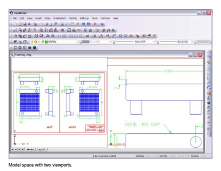
When you start a drawing session, your initial working area is called model space. Model space is an area in which you create two-dimensional and three-dimensional entities based on either the World Coordinate System (WCS) or a user coordinate system (UCS). You view and work in model space while using the Model tab.
Your view of this area is a single viewport that fills the screen. You can create additional views on the Model tab, called viewports, which can show the same or different two-dimensional or three-dimensional views, all of which are displayed in a tiled manner. You can work in only one of these viewports at a time on the Model tab, and you can print only the current viewport.
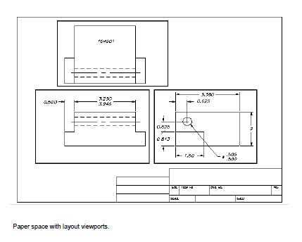
CADdirect 2022 provides an additional work area, called paper space. The contents of paper space represent the paper layout of your drawing. In this work area, you can create and arrange different views of your model similar to the way you arrange detail drawings or orthogonal views of a model on a sheet of paper. You can also add dimensions, keynotes, annotations, borders, title blocks, and other print-related entities in paper space, which reduces clutter when you work with your model in model space.
You view and work in paper space while using a Layout tab. Each view, or layout viewport, that you create in paper space provides a window of your drawing in model space. You can create one layout viewport or several. You can place layout viewports anywhere on the screen; their edges can be touching or not; and you can print them all at the same time.
You do not need to use paper space to print your drawing, but it offers several advantages:
- Print the same drawing with different print settings that you save with each layout, for example, printer configuration files, print style tables, lineweight settings, drawing scale, and more.
- Add print-related entities that are not essential to the model itself, such as key-notes or annotations, to reduce clutter when you work with your model in model space on the Model tab.
- For a single layout, create multiple layout viewports that print the model at different views and scales.
You can copy and move entities between model space and paper space.
Choose Modify > Change Space, then select the entities you want to copy or move from paper space to model space or from model space to paper space.
Viewing drawings in paper space and model space
When you work in paper space on a Layout tab, you can still view your drawing in model space. First you need to create a layout viewport in paper space; this allows you to view your model space entities from paper space.
Within a layout viewport you can modify and snap to model space entities while working in model space and even snap to model space entities from paper space. Snapping to model space entities from paper space allows you to accurately dimension model space entities in paper space. And although it is generally more convenient to modify entities on the Model tab, there are often times when it is convenient to make modifications from a layout viewport on a Layout tab.
Zooming or panning the drawing in model space or paper space affects the entire drawing, unless you use multiple windows or viewports. Additionally, if you are working from paper space, you can lock the layout viewport so the viewport scale and view center do not change while panning and zooming in the layout viewport.
To view a drawing in model space on the Model tab
Do one of the following:
- Click the Model tab.
- Right-click the Model/Paper Space toggle in the status bar, and then choose Model.
To view a drawing in paper space on a Layout tab
Do one of the following:
- Click one of the Layout tabs.
- Type layout and then press Enter. In the prompt box, choose Set. Type a name for the layout you want to make current, and then press Enter.
- Double-click the Model/Paper Space toggle in the status bar. For example, double-click “Model” or “M:Tab Name” in the status bar to switch to paper space.
- While using a Layout tab, type pspace and then press Enter.
- While using a Layout tab, double-click outside of the layout viewport.
- To view a drawing in model space on a Layout Tab Do one of the following:
- Click the desired Layout tab, and then create and view a layout viewport. For more details, see “Working with layout viewports” on page 456 in this chapter.
- Double-click the Model/Paper Space toggle in the status bar. For example, double-click “P:Tab Name” in the status bar to switch to model space on the current Lay-out tab.
- Type mspace and then press Enter.
- While using a Layout tab, double-click inside of the layout viewport.
Displaying the Model and Layout tab
The Model and Layout tabs can be hidden, if desired. You may want to hide the tabs if you only work on the Model tab or if you use the command bar and status bar to switch between tabs.
To turn the Model and Layout tabs display on or off
Do one of the following:
- On the ribbon, choose View > Model and Layout tabs (in Display).
- Choose View > Display > Model and Layout tabs.
- Choose Tools > Options > Display tab, and choose Show Tabs.
Creating a new layout
In CADdirect 2022, you can create multiple layouts for a single drawing. Each layout rep-resents a sheet of paper. For each layout, you can specify the print area, print styles, print scale, lineweight scale, pen mappings, and add viewports, dimensions, a title block, and other geometry specific to the layout.
The entities you add to a layout in paper space do not appear in model space.
Each layout requires at least one layout viewport, which is created automatically when you create a new layout. This viewport displays the drawing’s model space entities.
When you create a new drawing, the drawing automatically contains two default lay-outs: Layout1 and Layout2. You can start by using one of the default layouts, you can create your own, or you can create a new layout from another template (.dwt) file, drawing (.dwg) file, or drawing interchange (.dxf) file. You can also use CADdirect 2022 Explorer to create and manage layouts.
Each drawing can contain up to 255 layouts.
To create a new layout using the Layout1 or Layout2 tab
Click the Layout1 or Layout2 tab.
If necessary, set up at least one layout viewport. For details, see “Working with layout viewports” on page 456 in this chapter.
If desired, rename the layout. For details, see “To rename a layout” on page 455 in this chapter.
To create a new layout using a new Layout tab
Do one of the following to choose New Layout:
- On the ribbon, choose View > New Layout (in Layouts).
- Choose Insert > Layout > New Layout.
- On the Layouts toolbar, click the New Layout tool.
- Type layout, press Enter, and choose New.
Type a unique name for your layout and then press Enter.
The name can be up to 255 characters in length and can contain letters, numbers, the dollar sign ($), hyphen (-), and underscore (_), or any combination.
Set up at least one layout viewport. For details, see “Working with layout view-ports” on page 456 in this chapter.
To create a new layout from an existing file
Do one of the following: to choose Layout from Template On the ribbon, choose View > Layout from Template (in Layouts).
- On the menu, choose Insert > Layout > Layout from Template.
- On the Layouts toolbar, click the Layout from Template tool.
- Type layout, press Enter, and choose Template.
- Right-click a Layout tab and choose From Template.
Select the desired template, drawing, or drawing interchange file that contains the layout you want, and then click Open.
Select the layout(s), and then click OK. You can choose multiple layouts by holding down Ctrl while selecting layout names.
Reusing layouts from other files
Save time by reusing layouts that you have already created. Within the same drawing, you may want to make a copy of a layout that contains most of the settings you want, and then make changes to the new copy. If you created layouts that you want to use again when you create new drawings, you can save the layouts as a drawing template.
To make a copy of a layout
Type layout and then press Enter.
In the prompt box, choose Copy.
Type the name of the layout you want to copy, and then press Enter.
Type a name for the new layout, and then press Enter.
To save a layout as a drawing template
Type layout and then press Enter.
In the prompt box, choose Save.
Type the name of the layout that you want to save, and then press Enter.
Specify the file name and location for the template, and then click Save.
After you save a layout as a template, you can use the template when you create new drawings. You can also import the template’s layouts into another drawing.
Managing layouts in a drawing
You can rename layouts, delete layouts, and view a list of all layouts available in a drawing. You can also change the order in which the Layout tabs appear; the Model tab is always stationary.
If you want to rename, delete, or reorder a layout when the Layout tabs are hidden, you can type layout to make your changes or choose View > Display > Model and Layout Tabs to display the tabs.
To rename a layout
Right-click the Layout tab to rename.
Type a new name for the layout.
Click OK.
The name can be up to 255 characters in length and can contain letters, numbers, the dollar sign ($), hyphen (-), and underscore (_), or any combination.
To delete a layout
Right-click the Layout tab to delete.
Click OK to confirm the deletion.
You cannot delete the Model tab or the last remaining Layout tab.
To delete all geometry from the Model tab or a Layout tab, first select all geometry and then use the Erase command.
To reorder the Layout tabs
Right-click the Layout tab you want to move.
Do one of the following:
- Choose Move Right, and then choose a new location.
- Choose Move Left, and then choose a new location.
To view a list of all layouts
Type layout and then press Enter.
In the prompt box, choose ? to list all layouts.
Type s or press Enter to scroll through the layouts.
Working with layout viewports
A layout viewport is a window in a Layout tab (paper space) that displays all or a portion of a drawing’s model space entities.
14.2.9 Understanding layout viewports
When you begin working in a drawing on the Model tab, it consists of a single view of your model. You may have created additional views by dividing the drawing space into multiple windows; each window is a separate viewport on the Model tab.
Similarly, when you begin working in a drawing on a Layout tab, it consists of a single view from paper space of your model. You can also create multiple layout view-ports that display unique views of your model. Each layout viewport functions as a window into your model space drawing — with each window looking different from the next. You can customize the view center, scale, layer visibility, and contents of each layout viewport. Each layout viewport is created as a separate entity that you can move, copy, or delete.
Click any layout viewport to make it the current viewport, and then add or modify model space entities in that viewport, even while snapping to model space entities from paper space. Any changes you make in one layout viewport are immediately visible in the other viewports (if the other layout viewports are displaying that portion of the drawing). Zooming or panning in the current viewport affects only that view-port.
This section focusses on working with layout viewports in paper space on a Layout tab. For additional information about viewports in model space, see “Dividing the current window into multiple views” on page 172.
Creating layout viewports
The first time you switch to a Layout tab, your model displays in a default layout viewport. You can create other layout viewports anywhere inside the drawing area. You can control the number of viewports created and the arrangement of the view-ports.
To create layout viewports
Do one of the following to choose Layout Viewports:
- On the ribbon, choose View > Layout Viewports (in Layouts).
- On the menu, choose View > Viewports > Layout Viewports.
- On the Viewports toolbar, click the Layout Viewports tool.
- Type mview and then press Enter.
Specify two opposing corners to create a custom rectangular viewport, or in the prompt box, choose one of the following:
- Fit To View — Creates a layout viewport that fills the screen.
- Entity — Converts a closed entity to a layout viewport. You can convert a circle, ellipse, closed polyline, spline, or region.
- Polygonal — Creates a non-rectangular layout viewport.
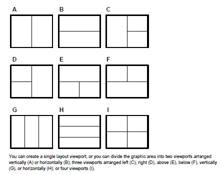
- Create 2 Viewports, Create 3 Viewports, Create 4 Viewports — Creates two, three, or four layout viewports using an orientation that you specify. You can select whether to arrange the viewports to fill the current graphic area or a rectangular area that you specify.
The border of a new layout viewport is created on the current layer.
You can make layout viewport borders invisible by creating a new layer before you create layout viewports and then turning off that layer after you create the layout viewports. To select a layout viewport’s borders, you must turn that layer back on before you can rearrange or modify the layout viewport.
Viewing and scaling layout viewports
If you have created numerous layout viewports, your system performance may be affected. If necessary, you can turn a layout viewport on or off. Turning off a layout viewport does not delete the viewport or its contents; it simply turns off its display.
You can also change how you view items within a layout viewport by specifying a scale factor, which changes how large or small model space entities appear within the layout viewport.
While working in a layout viewport, you can use the Maximize Viewport command to enlarge the view to full size and emulate model space, allowing you to easily work on the geometry in that view. When done, use the Minimize Viewport command to switch back to the original scale and center point of the layout viewport.
To turn layout viewports on or off
Click the desired Layout tab.
Do one of the following to choose Layout Viewports:
- On the ribbon, choose View > Layout Viewports (in Layouts).
- On the menu, choose View > Viewports > Layout Viewports.
- On the Viewports toolbar, click the Layout Viewports tool.
- Type mview and then press Enter.
Choose On or Off.
Select the edge of the layout viewport to turn on or off, and then press Enter.
To maximize a layout viewport
On a Layout tab, select a layout viewport. Or, skip this step to maximize the cur-rent layout viewport.
Do one of the following:
- On the ribbon, choose View > Maximize Viewport (in Model Viewports).
- On the menu, choose View > Viewports > Maximize Viewport.
- On the status bar, click Maximize Viewport.
- Type vpmax and then press Enter.
The layout viewport is enlarged.
To minimize a layout viewport (if it is maximized)
Do one of the following:
- On the ribbon, choose View > Minimize Viewport (in Model Viewports).
- On the menu, choose View > Viewports > Minimize Viewport.
- On the status bar, click Minimize Viewport.
- Type vpmin and then press Enter.
The layout viewport returns to its original scale and centerpoint.
To change the layout viewport scale
Do one of the following to choose Properties:
- On the ribbon, choose View > Properties (in Display).
- On the menu, choose Modify > Properties.
- On the Modify toolbar, click the Properties tool.
- Type entprop and then press Enter.
Select the edge of the layout viewport.
In Custom Scale, enter the scale at which you want to view model space entities from within the layout viewport.
Click OK.
To change the scale of model space entities relative to paper space
Click the Model tab.
Click a viewport to make it current.
Choose View > Zoom > Zoom.
Type the zoom scale factor relative to paper space by appending the suffix xp to the scale factor, and then press Enter.
For example, to increase the scale of the entities in the viewport on the Model tab to twice the size of paper space units, type 2xp. To decrease the scale to half the size of paper space units, type .5xp.
Modifying layout viewports
After you create layout viewports, you can modify them as needed. On the Layout tab, you can snap to the viewport borders using entity snaps. You can copy, delete, move, scale, and stretch layout viewports as you would any other drawing entity.
Additionally, you can lock a layout viewport so the viewport scale and view center do not change in model space while panning or zooming in the layout viewport. If you are working on model space entities from a Layout tab, locking the layout viewport prevents you from constantly changing the layout viewport scale and view center.
And assigning a UCS to each viewport allows you to quickly switch between layout viewports and immediately draw in a different UCS. This can greatly increase productivity, especially when creating complex 3D models.
Modifying a layout viewport on a Layout tab does not affect the model space entities within the layout viewport.
To modify layout viewport properties
Click the desired Layout tab.
Do one of the following to choose Properties:
- On the ribbon, choose View > Properties (in Display).
- On the menu, choose Modify > Properties.
- On the Modify toolbar, click the Properties tool.
- Type entprop and then press Enter.
Select the edge of the layout viewport you want to modify.
Adjust the center point, width, or height of the viewport.
In Custom Scale, enter the scale at which you want to view model space entities from within the layout viewport.
In Display Locked, choose True to lock the viewport scale and view in model space while panning or zooming in the layout viewport.
Mark UCS per Viewport if you want to use a unique UCS for each layout view-port.
Click OK.
You can select only layout viewports for modification.
If you click a viewport on the Model tab, it makes that viewport active, not available for modification.
Clipping layout viewports
You can clip layout viewports so that only a portion of the viewport is visible on a Layout tab. You can clip layout viewports in the shape of a new polygon or an existing circle, ellipse, closed spline, closed polyline, or region.
If you delete clipping from a layout viewport, the clipping is removed permanently but the viewport itself and its contents remain in the drawing.
To clip a layout viewport in the shape of an existing entity
Click a Layout tab, and select the desired layout viewport.
Type vpclip and then press Enter.
In the drawing, select an existing circle, ellipse, closed spline, closed polyline, or region to use as a clipping boundary.
To clip a layout viewport in the shape of a new polygon
Click a Layout tab, and select the desired layout viewport.
Type vpclip and then press Enter.
Press Enter to create a new clipping boundary.
Define the first point of the clipping polygon.
Define additional points.
Press Enter when done.
To delete a clipping boundary
Click a Layout tab, and select the desired layout viewport.
Type vpclip and then press Enter.
Choose Delete, and then press Enter.
© Copyright 2021 BackToCAD Technolgies LLC . All rights reserved. Kazmierczak® is a registered trademark of Kazmierczak Software GmbH. CADdirect 2022 is a trademark of Expert Robotics Inc. Print2CAD and CAD2Print are Trademarks of BackToCAD Technologies LLC. DWG is the name of Autodesk’s proprietary file format and technology used in AutoCAD® software and related products. Autodesk, the Autodesk logo, AutoCAD, DWG are registered trademarks or trademarks of Autodesk, Inc., and/or its subsidiaries and/or affiliates in the USA and/or other countries. All other brand names, product names, or trademarks belong to their respective holders. This website is independent of Autodesk, Inc., and is not authorized by, endorsed by, sponsored by, affiliated with, or otherwise approved by Autodesk, Inc. The material and software have been placed on this Internet site under the authority of the copyright owner for the sole purpose of viewing of the materials by users of this site. Users, press, or journalists are not authorized to reproduce any of the materials in any form or by any means, electronic or mechanical, including data storage and retrieval systems, recording, printing or photocopying.