BackToCAD Technologies LLC | Artificial Intelligence and Software Developing | Clearwater, USA; Stuttgart, Germany | Kazmierczak® Company
Drawing multilines
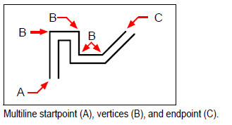
A multiline is made from multiple parallel lines (two lines by default), which consist
of linear segments connected together. The end of the current segment is the start of
the next segment. Ends of segments are the vertices of the multiline.
To draw a multiline
1 Do one of the following to choose Multiline ( ):
• On the ribbon, choose Draw > Multiline.
• On the menu, choose Draw > Multiline.
• On the Draw toolbar, click the Multiline tool.
• Type mline and then press Enter.
2 Specify the start point.
3 Specify additional vertices.
4 After specifying the last endpoint, choose Done or press Enter.
Specifying justification and scale
When you draw a multiline, you specify the vertices of one of the lines that makes up
the multiline — the additional parallel lines are drawn in position according to the
justification. Vertices can be specified on the top, middle, or bottom of a multiline,
according to the selected justification.
You can also determine the overall width of the multiline, which affects the distance
between parallel lines, by adjusting the multiline scale.
NOTE If you change the multiline scale, you might need to make equivalent changes to
the linetype scale to prevent dots or dashes from being disproportionately sized.
.
To draw a multiline with different justification or scale
1 Do one of the following to choose Multiline:
• On the ribbon, choose Draw > Multiline.
• On the menu, choose Draw > Multiline.
• On the Draw toolbar, click the Multiline tool.
• Type mline and then press Enter.
2 Select justification and choose one of the following options:
• Top Specified vertices define the top line; additional parallel lines are drawn below the specified vertices.
• Zero Specified vertices define the middle of the multiline.
• Bottom Specified vertices define the bottom line; additional parallel lines are drawn above the specified vertices.
3 Select Scale and enter a new scale value according to the following:
• Greater than 1 — Multilines are wider.
• Less than 1 — Multilines are narrower.
• Equal to 1 — Multilines collapse into a single line.
• Negative value — Flips the justification when multilines are drawn and alters the scale according to the set value.
4 Specify the start point of the multiline.
5 Specify additional vertices.
6 After specifying the endpoint, choose Done or press Enter.
© Copyright 2021 BackToCAD Technolgies LLC . All rights reserved. Kazmierczak® is a registered trademark of Kazmierczak Software GmbH. CADdirect 2022 is a trademark of Expert Robotics Inc. Print2CAD and CAD2Print are Trademarks of BackToCAD Technologies LLC. DWG is the name of Autodesk’s proprietary file format and technology used in AutoCAD® software and related products. Autodesk, the Autodesk logo, AutoCAD, DWG are registered trademarks or trademarks of Autodesk, Inc., and/or its subsidiaries and/or affiliates in the USA and/or other countries. All other brand names, product names, or trademarks belong to their respective holders. This website is independent of Autodesk, Inc., and is not authorized by, endorsed by, sponsored by, affiliated with, or otherwise approved by Autodesk, Inc. The material and software have been placed on this Internet site under the authority of the copyright owner for the sole purpose of viewing of the materials by users of this site. Users, press, or journalists are not authorized to reproduce any of the materials in any form or by any means, electronic or mechanical, including data storage and retrieval systems, recording, printing or photocopying.