BackToCAD Technologies LLC | Artificial Intelligence and Software Developing | Clearwater, USA; Stuttgart, Germany | Kazmierczak® Company
Editing polylines
You can modify any type of two-dimensional or three-dimensional polyline. Entities such as rectangles, polygons, and donuts, as well as three-dimensional entities such as pyramids, cylinders, and spheres, are all variations of polylines that you can edit.
You can edit a polyline by opening or closing it, by changing its overall width or the widths of individual segments, and by converting a polyline with straight line segments into a flowing curve or an approximation of a spline. In addition, you can use the Edit Polyline tool to edit individual vertices, adding, removing, or moving vertices. You can also add new segments to an existing polyline, change the linetypes of a polyline, and reverse the direction or order of the vertices.
Converting an entity to a polyline
To modify a polyline, you first select the polyline, and then select a polyline editing option. The available options vary depending on whether the selected polyline is a two-dimensional or three-dimensional entity. If the selected entity is not a polyline, the Edit Polyline tool provides the option of turning it into one. You can convert only arcs and lines into polylines. If several arcs or lines are joined endpoint to endpoint, they can all be selected and turned into one polyline.
To convert an entity into a polyline
Do one of the following to choose Edit Polyline:
- On the ribbon, choose Edit > Edit Polyline (in Modify).
- On the menu, choose Modify > Entities > Polyline.
- On the Modify toolbar, click the Edit Polyline tool.
- Type editpline and then press Enter.
Select the entity.
In the prompt box, choose Yes-Turn Into Polyline.
In the prompt box, choose another option, or choose Done to complete the command.
Opening and closing polylines
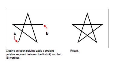
When you close a polyline, the program draws a straight polyline segment from the last vertex of the polyline to the first vertex. Opening a polyline removes the closing segment. When you select a polyline for editing, the prompt box displays either the Open or Close option, depending on whether the polyline you select is closed or open.
To close an open polyline
Do one of the following to choose Edit Polyline:
- On the ribbon, choose Edit > Edit Polyline (in Modify).
- On the menu, choose Modify > Entities > Polyline.
- On the Modify toolbar, click the Edit Polyline tool.
- Type editpline and then press Enter.
Select the polyline.
In the prompt box, choose Close.
In the prompt box, choose another option, or choose Done to complete the command.
Curving and recurving polylines
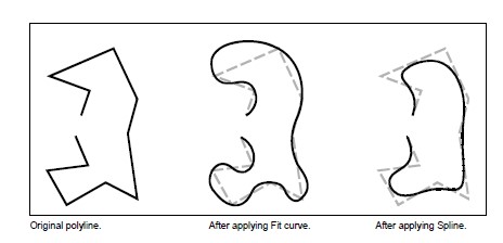
You can convert a multi-segment polyline into a smooth curve using either the Fit or Spline option. The Fit option creates a smooth curve connecting all the vertices. The Spline option computes a smooth curve that is pulled toward the vertices but passes through only the first and last vertices. The Decurve option removes Fit or Spline curves and arcs, leaving straight segments between the vertices.
To fit a curve to a polyline
Do one of the following to choose Edit Polyline:
- On the ribbon, choose Edit > Edit Polyline (in Modify).
- On the menu, choose Modify > Entities > Polyline.
- On the Modify toolbar, click the Edit Polyline tool.
- Type editpline and then press Enter.
Select the polyline.
In the prompt box, choose Fit.
In the prompt box, choose another option, or choose Done to complete the command.
Joining polylines
You can add an arc, line, or polyline entity to an existing open polyline, forming one continuous polyline entity. To join an entity to a polyline, that entity must already share an endpoint with an end vertex of the selected polyline.
When you join an entity to a polyline, the width of the new polyline segment depends on the width of the original polyline and the type of entity you are joining to it:
- A line or an arc assumes the same width as the polyline segment for the end vertex to which it is joined.
- A polyline joined to a tapered polyline retains its own width values.
- A polyline joined to a uniform-width polyline assumes the width of the polyline to which it is joined.
To join an arc, line, or polyline to an existing polyline
Do one of the following to choose Edit Polyline:
- On the ribbon, choose Edit > Edit Polyline (in Modify).
- On the menu, choose Modify > Entities > Polyline.
- On the Modify toolbar, click the Edit Polyline tool.
- Type editpline and then press Enter.
Select the polyline.
In the prompt box, choose Join.
Select the arc, line, or polyline to join.
In the prompt box, choose another option, or choose Done to complete the command.
Changing the polyline width
You can change the width of an entire polyline, applying a uniform width to the entire entity or tapering the polyline uniformly along its entire length.
To apply a uniform width to an entire polyline
Do one of the following to choose Edit Polyline:
- On the ribbon, choose Edit > Edit Polyline (in Modify).
- On the menu, choose Modify > Entities > Polyline.
- On the Modify toolbar, click the Edit Polyline tool.
- Type editpline and then press Enter.
Select the polyline.
In the prompt box, choose Width.
Specify the new polyline width.
In the prompt box, choose another option, or choose Done to complete the command.
To taper a polyline uniformly along its length
Do one of the following to choose Edit Polyline:
- On the ribbon, choose Edit > Edit Polyline (in Modify).
- On the menu, choose Modify > Entities > Polyline.
- On the Modify toolbar, click the Edit Polyline tool.
- Type editpline and then press Enter.
Select the polyline.
In the prompt box, choose Taper.
Specify the starting width.
Specify the ending width.
In the prompt box, choose another option, or choose Done to complete the command.
Editing polyline vertices
You can use the Edit Vertices option to modify individual polyline vertices. When you select this option, the program switches into a special vertex editing mode and places an x on the first vertex. The x indicates the vertex you are editing. The Next and Previous options move the x to the next or previous vertex. You can edit only one vertex at a time.
When editing vertices, you can modify the polyline in the following ways:
- Convert a polyline segment into a curve by specifying a new tangent angle.
- Break a polyline into two separate polylines.
- Insert a new vertex after the current vertex.
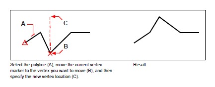
- Move the current vertex.
- Straighten the polyline segment between two vertices.
- Change the width of the polyline segment between two vertices.
To move a polyline vertex
Do one of the following to choose Edit Polyline:
- On the ribbon, choose Edit > Edit Polyline (in Modify).
- On the menu, choose Modify > Entities > Polyline.
- On the Modify toolbar, click the Edit Polyline tool.
- Type editpline and then press Enter.
Select the polyline.
In the prompt box, choose Edit Vertices.
In the prompt box, choose Next Vertex.
Repeat until the x reaches the vertex you want to move.
In the prompt box, choose Move.
Specify the new location for the vertex.
In the prompt box, choose another option, or choose Exit to stop editing vertices.
In the prompt box, choose another option, or choose Done to complete the command.
To taper the width of an individual polyline segment
Do one of the following to choose Edit Polyline:
- On the ribbon, choose Edit > Edit Polyline (in Modify).
- On the menu, choose Modify > Entities > Polyline.
- On the Modify toolbar, click the Edit Polyline tool.
- Type editpline and then press Enter.
Select the polyline.
In the prompt box, choose Edit Vertices.
In the prompt box, choose Next Vertex.
Repeat until the x reaches the first vertex of the segment you want to taper.
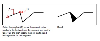
In the prompt box, choose Width.
Specify the starting width.
Specify the ending width.
In the prompt box, choose another option, or choose Exit to stop editing vertices and update the display.
In the prompt box, choose another option, or choose Done to complete the command.
© Copyright 2021 BackToCAD Technolgies LLC . All rights reserved. Kazmierczak® is a registered trademark of Kazmierczak Software GmbH. CADdirect 2022 is a trademark of Expert Robotics Inc. Print2CAD and CAD2Print are Trademarks of BackToCAD Technologies LLC. DWG is the name of Autodesk’s proprietary file format and technology used in AutoCAD® software and related products. Autodesk, the Autodesk logo, AutoCAD, DWG are registered trademarks or trademarks of Autodesk, Inc., and/or its subsidiaries and/or affiliates in the USA and/or other countries. All other brand names, product names, or trademarks belong to their respective holders. This website is independent of Autodesk, Inc., and is not authorized by, endorsed by, sponsored by, affiliated with, or otherwise approved by Autodesk, Inc. The material and software have been placed on this Internet site under the authority of the copyright owner for the sole purpose of viewing of the materials by users of this site. Users, press, or journalists are not authorized to reproduce any of the materials in any form or by any means, electronic or mechanical, including data storage and retrieval systems, recording, printing or photocopying.