BackToCAD Technologies LLC | Artificial Intelligence and Software Developing | Clearwater, USA; Stuttgart, Germany | Kazmierczak® Company
Editing three-dimensional solids (Professional Version Only)
You can edit three-dimensional solids in several unique ways, including: chamfer, fil-let, section, and slice. You can also modify individual faces and edges of solids, as well as imprint, separate, shell, and check solids.
You can edit three-dimensional ACIS solids, including: boxes, cones, cylinders, dishes, domes, pyramids, spheres, tori, and wedges.
Chamfering and filleting solids (Pro Version Only)
You can chamfer or fillet a three-dimensional solid much like you chamfer or fillet a two-dimensional entity.
To chamfer a solid (Pro Version Only)
Do one of the following to choose Chamfer:
- On the ribbon, choose Edit > Chamfer (in Modify).
- On the menu, choose Modify > Chamfer.
- On the Modify toolbar, click the Chamfer tool.
- Type chamfer and then press Enter.
Select the edge of the base surface to chamfer. (One of two surfaces adjacent to the selected edge will be highlighted.)
Do one of the following:
- To select a different surface, type n and press Enter.
- To use the current surface, press Enter.
Specify the base surface distance (measured from the selected edge to the base surface).
Specify the adjacent surface distance (measured from the selected edge to the adjacent surface).
Do one of the following:
- Specify the edges to chamfer.
- To select all edges around the base surface, type l and press Enter.
To fillet a solid (Pro Version Only)
Do one of the following to choose Fillet:
- On the ribbon, choose Edit > Fillet (in Modify).
- On the menu, choose Modify > Fillet.
- On the Modify toolbar, click the Fillet tool.
- Type fillet and then press Enter.
Select the edge of the solid to fillet.
Specify the fillet radius.
Select additional edges to fillet, and press Enter to fillet.
Sectioning and slicing solids (Pro Version Only)
You can section or slice a three-dimensional solid, region, or body (typically a sheet).
When you section a solid, you obtain an “inside view” by creating a cross-section through the solid as a region or block. When you section a region or body, the resulting intersections are curves.
When you slice a solid, region, or body, you create a new entity by cutting the original entity and removing a specific side.
To section an entity (Pro Version Only)
Do one of the following to choose Section:
- On the ribbon, choose Draw 3D > Section (in Draw 3D Solids).
- On the menu, choose Draw > 3D Solids > Section.
- On the Draw 3D Solids toolbar, click the Section tool.
- Type section and then press Enter.
Select the entities to cross-section.
Do one of the following:
- Specify three points to define the cross-section plane. (The first point defines the origin, while the second point defines the x-axis and the third point defines the y-axis.)
- Type o and press Enter to select an entity that defines the cross-sectional plane.
- Specify an axis by typing the appropriate letter and pressing Enter.
To slice an entity (Pro Version Only)
Do one of the following to choose Slice:
- On the ribbon, choose Draw 3D > Slice (in Draw 3D Solids).
- On the menu, choose Draw > 3D Solids > Slice.
- On the Draw 3D Solids toolbar, click the Slice tool.
- Type slice and then press Enter.
Select the entities to slice.
Do one of the following:
- Specify three points to define the cross-section plane. (The first point defines the origin, while the second point defines the x-axis and the third point defines the y-axis.)
- Type o and press Enter to select an entity that defines the cross-sectional plane.
- Specify an axis by typing the appropriate letter and pressing Enter.
Specify which side to retain, or type b to retain both sides.
Modifying faces (Pro Version Only)
You can edit three-dimension solids by extruding, moving, rotating, offsetting, tapering, deleting, or copying individual faces. You can also change the color of individual faces.
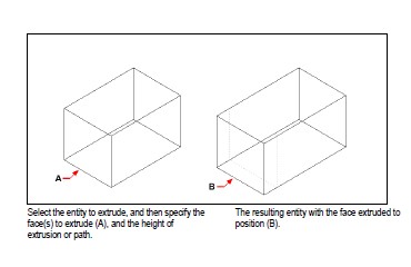
Extruding solid faces
To extrude a solid face (Pro Version Only)
Do one of the following to choose Extrude Face:
- On the ribbon, choose Draw 3D > Extrude Face (in Solids Editing).
- On the menu, choose Modify > Solids Editing > Extrude Face.
- On the Solids Editing toolbar, click the Extrude Face tool.
Select the entity with the face you want to extrude.
Select the face(s) to extrude, and press Enter.
Do one of the following:
Specify the height of extrusion.
Type p and press Enter to select a path for extrusion.
If you specified a height, specify a taper angle.
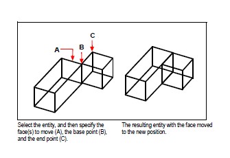
Moving solid faces
Do one of the following to choose Move Face:
- On the ribbon, choose Draw 3D > Move Face (in Solids Editing).
- On the menu, choose Modify > Solids Editing > Move Face.
- On the Solids Editing toolbar, click the Move Face tool.
Select the entity with the face you want to move.
Select the face(s) to move, and press Enter.
Specify a base point.
Specify an end point.
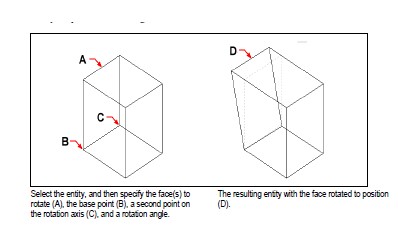
Rotating solid faces
To rotate a solid face (Pro Version Only)
Do one of the following to choose Rotate Face:
- On the ribbon, choose Draw 3D > Rotate Face (in Solids Editing).
- On the menu, choose Modify > Solids Editing > Rotate Face.
- On the Solids Editing toolbar, click the Rotate Face tool.
Select the entity with the face you want to rotate.
Select the face(s) to rotate, and press Enter.
Specify a base point.
Specify another point on the rotation axis.
Specify the rotation angle.
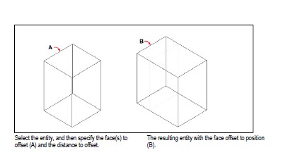
Offsetting solid faces
To offset a solid face (Pro Version Only)
Do one of the following to choose Offset Face:
- On the ribbon, choose Draw 3D > Offset Face (in Solids Editing).
- On the menu, choose Modify > Solids Editing > Offset Face.
- On the Solids Editing toolbar, click the Offset Face tool.
Select the entity with the face you want to offset.
Select the face(s) to offset, and press Enter.
Specify an offset distance.
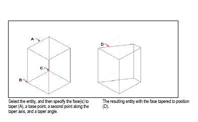
Tapering solid faces
To taper a solid face (Pro Version Only)
Do one of the following to choose Taper Face:
- On the ribbon, choose Draw 3D > Taper Face (in Solids Editing).
- On the menu, choose Modify > Solids Editing > Taper Faces.
- On the Solids Editing toolbar, click the Taper Face tool.
Select the entity with the face you want to taper.
Select the face(s) to taper, and press Enter.
Specify a base point.
Specify another point along the axis.
Specify a taper angle.
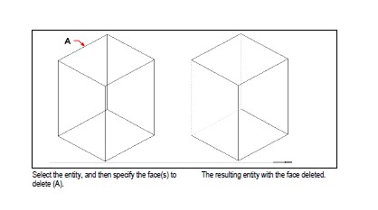
Deleting solid faces
To delete a solid face (Pro Version Only)
Do one of the following to choose Delete Face:
- On the ribbon, choose Draw 3D > Delete Face (in Solids Editing).
- On the menu, choose Modify > Solids Editing > Delete Face.
- On the Solids Editing toolbar, click the Delete Face tool.
Select the entity with the face you want to delete.
Select the face(s) to delete, and press Enter.
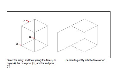
Copying solid faces
To copy a solid face (Pro Version Only)
Do one of the following to choose Copy Face:
- On the ribbon, choose Draw 3D > Copy Face (in Solids Editing).
- On the menu, choose Modify > Solids Editing > Copy Face.
- On the Solids Editing toolbar, click the Copy Face tool.
Select the entity with the face you want to copy.
Select the face(s) to copy, and press Enter.
Specify a base point.
Specify an end point.
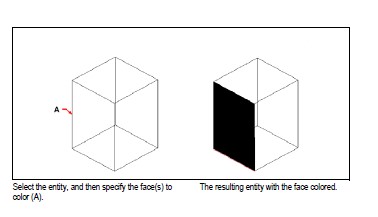
Coloring solid faces
To color a face (Pro Version Only)
Do one of the following to choose Color Face:
- On the ribbon, choose Draw 3D > Color Face (in Solids Editing).
- On the menu, choose Modify > Solids Editing > Color Face.
- On the Solids Editing toolbar, click the Color Face tool.
Select the entity with the face you want to color.
Select the face(s) to color, and press Enter.
Specify a color.
Modifying edges (Pro Version Only)
In addition to modifying faces of solids, you can modify individual edges. You can copy individual edges or change the color of individual edges.
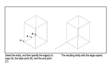
To copy an edge (Pro Version Only)
Do one of the following to choose Copy Edge:
- On the ribbon, choose Draw 3D > Copy Edge (in Solids Editing).
- On the menu, choose Modify > Solids Editing > Copy Edge.
- On the Solids Editing toolbar, click the Copy Edge tool.
Select the entity with the edge you want to copy.
Select the edge(s) to copy, and press Enter.
Specify a base point.
Specify an end point.
To color an edge (Pro Version Only)
Do one of the following to choose Color Edge:
- On the ribbon, choose Draw 3D > Color Edge (in Solids Editing).
- On the menu, choose Modify > Solids Editing > Color Edge.
- On the Solids Editing toolbar, click the Color Edge tool.
Select the entity with the edge you want to color.
Select the edge(s) to color, and press Enter.
Specify a color.
Imprinting solids (Pro Version Only)
You can modify the face of a solid by imprinting another entity on it. For example, you can imprint a line, arc, or polyline onto the face of a box.
To imprint a solid entity (Pro Version Only)
Do one of the following to choose Imprint:
- On the ribbon, choose Draw 3D > Imprint (in Solids Editing).
- On the menu, choose Modify > Solids Editing > Imprint.
- On the Solids Editing toolbar, click the Imprint tool.
Select the solid entity you want to imprint.
Select the entity you want to imprint on the solid.
Separating solids
You can separate solids that have been combined. After you separate them, they are separated into individual solids.
To separate solids (Pro Version Only)
Do one of the following to choose Separate:
- On the ribbon, choose Draw 3D > Separate (in Solids Editing).
- On the menu, choose Modify > Solids Editing > Separate.
- On the Solids Editing toolbar, click the Separate tool.
Select the solid you want to separate.
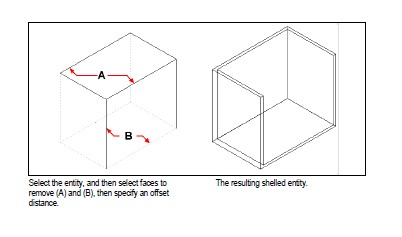
Shelling solids (Pro Version Only)
You can create a shell or a hollow thin wall from your 3D solid entity. CADdirect 2022 offsets existing faces to create new faces.
To shell a solid (Pro Version Only)
Do one of the following to choose Shell:
- On the ribbon, choose Draw 3D > Shell (in Solids Editing).
- On the menu, choose Modify > Solids Editing > Shell.
- On the Solids Editing toolbar, click the Shell tool.
Select the entity you want to shell.
Remove any faces you don’t want to include.
Specify an offset distance.
Cleaning solids (Pro Version Only)
You can remove redundant edges or vertices from solids when they are not needed.
To clean a solid (Pro Version Only)
Do one of the following to choose Clean:
- On the ribbon, choose Draw 3D > Clean (in Solids Editing).
- On the menu, choose Modify > Solids Editing > Clean.
- On the Solids Editing toolbar, click the Clean tool.
Select the entity you want to clean.
Checking solids (Pro Version Only)
You can check whether a selected entity is a valid three-dimensional ACIS solid. If it is a valid 3D solid, you can modify the entity using the 3D solid editing commands; if not, you cannot edit the entity using these commands.
To check a solid (Pro Version Only)
Do one of the following to choose Check:
- On the ribbon, choose Draw 3D > Check (in Solids Editing).
- On the menu, choose Modify > Solids Editing > Check.
- On the Solids Editing toolbar, click the Check tool.
Select the entities to check.
Converting solids to polyface meshes (Pro Version Only)
You can convert three-dimensional solids to polyface meshes using the 3DConvert command.
To convert a solid (Pro Version Only)
Type 3dconvert and press Enter.
Select the entities you want to convert.
© Copyright 2021 BackToCAD Technolgies LLC . All rights reserved. Kazmierczak® is a registered trademark of Kazmierczak Software GmbH. CADdirect 2022 is a trademark of Expert Robotics Inc. Print2CAD and CAD2Print are Trademarks of BackToCAD Technologies LLC. DWG is the name of Autodesk’s proprietary file format and technology used in AutoCAD® software and related products. Autodesk, the Autodesk logo, AutoCAD, DWG are registered trademarks or trademarks of Autodesk, Inc., and/or its subsidiaries and/or affiliates in the USA and/or other countries. All other brand names, product names, or trademarks belong to their respective holders. This website is independent of Autodesk, Inc., and is not authorized by, endorsed by, sponsored by, affiliated with, or otherwise approved by Autodesk, Inc. The material and software have been placed on this Internet site under the authority of the copyright owner for the sole purpose of viewing of the materials by users of this site. Users, press, or journalists are not authorized to reproduce any of the materials in any form or by any means, electronic or mechanical, including data storage and retrieval systems, recording, printing or photocopying.