BackToCAD Technologies LLC | Artificial Intelligence and Software Developing | Clearwater, USA; Stuttgart, Germany | Kazmierczak® Company
Hiding, shading, and rendering
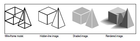
As you create three-dimensional entities, the program displays both wire-frame and surface models in wire-frame view, which makes it difficult to visualize your three-dimensional models. To better visualize the model, you can remove all the lines that are hidden behind other entities or surfaces when seen from the current viewpoint.
Shading goes a step further by removing hidden lines and then assigning flat colors to the visible surfaces, making them appear solid. Shaded images are useful when you want to quickly visualize your model as a solid entity, though they lack depth and definition.
Rendering provides an even more realistic image of your model, complete with light sources, shadows, surface material properties, and reflections, giving your model a photo-realistic look. As shown in the following illustrations, when you render a model, the program removes hidden lines and then shades the surfaces as though they were illuminated from imaginary light sources.
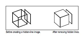
Creating hidden-line images
Creating a hidden-line view of your drawing removes all the lines that are hidden behind other surfaces when seen from your vantage point. When you remove hidden lines or shade a model, the program treats the entities differently, depending on how you created them. Wire-frame models always appear transparent, because they have no surfaces. Surface models appear filled, with surfaces applied to all visible sides.
To create a hidden-line image
Type hide and then press Enter.
Use a visual style.
Choosing View > Visual Styles > 3D Hidden is similar to using the Hide command. For more details, see “Displaying a drawing with a visual style” on page 170.
Creating shaded images
Creating a shaded image of your drawing removes hidden lines and then applies shading to the visible surfaces based on their entity color. Because they are intended to provide a quick visualization, shaded images do not have a light source and use continuous colors across surfaces, causing them to appear flat and unrealistic.
To create a shaded image
Type shade and then press Enter. To control the appearance of the shaded image, choose Tools > Drawing Settings, and then click the 3D Settings tab and select the options you want. You can shade the surfaces and edges of the model in four ways:
- Faces shaded; edges not highlighted.
- Faces shaded; edges highlighted in the background color.
- Faces filled in the background color; edges drawn using the entity color (similar to a hidden-line view).
- Faces filled using the entity color; edges highlighted in the background color.
- Use a visual style.
Choosing View > Visual Styles > 3D Realistic is similar to using the Shade command. For more details, see “Displaying a drawing with a visual style” on page 170.
Creating rendered images
Creating a rendered image of your drawing removes hidden lines and then shades the surface as though it were illuminated from multiple light sources.
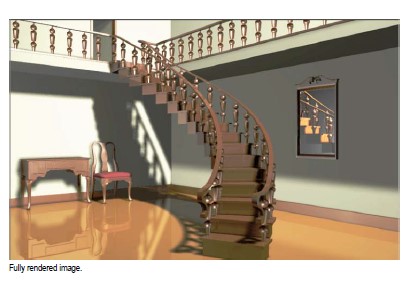
Full rendering creates a photo-realistic image of your model, complete with light sources, shadows, surface material properties, and reflections. You can illuminate your image with spotlights, distant lighting to simulate sunshine, and ambient light. If you choose not to customize the light sources, the program generates default light sources for you.
Rays from these imaginary light sources are traced as they reflect off and refract through the surfaces of the model, a process called ray tracing. Ray tracing deter-mines where shadows fall and how reflections on shiny materials such as metal and glass appear. You can modify the reflective properties of the materials that make up your model to control how the light rays reflect off its surfaces.
Full rendering automatically creates a base on which your model is displayed, if you don’t already have one, so it does not appear suspended in space. A background is also automatically added to the image. A background such as a cloudy sky or an imported raster graphic such as a stone wall can also be added behind the image, making it even more realistic.
To create a quickly rendered image
Do one of the following to choose Render:
- On the ribbon, choose View > Render Settings (in Rendering).
- On the menu, choose View > Rendering > Render.
- On the Rendering toolbar, click the Render tool.
- Type render and then press Enter.
To create a fully rendered image
Do one of the following to choose Full Render:
- On the ribbon, choose View > Render Settings (in Rendering).
- On the menu, choose View > Rendering > Full Render.
- On the Rendering toolbar, click the Full Render tool.
- Type fullrender and then press Enter.
Creating custom rendered images
CADdirect 2022 allows you to create custom rendered images by applying materials, backgrounds, and lighting (including shadows) to your drawing:
- Materials Specify materials for different surfaces and define how the materials map to those surfaces. Predefined materials are available in the materials library, which can be customized further using the built-in editor. You can choose to use procedural or bitmap materials.
- Backgrounds Specify the background or backdrop for a rendered image. Several predefined backgrounds are available. By default, no background is used, and it appears black. The background is an infinite, planar surface and reflects off of any reflective surfaces in your model. The background is not affected by lighting how-ever, so no shadows or highlights are seen on the background.
- Lighting Specify the placement of lights, light color, and light intensity to deter-mine how your drawing or scene is lit, including shadows and reflections in the scene. Lights can be placed either outside the field of view or inside to illuminate different areas of the scene. Several predefined lighting controls are available, including ambient lighting, diffuse lighting, specular reflections, specular high-lights, and transparency.
To apply materials, backgrounds, and lighting
Do one of the following to choose Materials, Backgrounds, or Lighting:
- On the ribbon, choose View > Materials, Backgrounds, or Lighting (in Rendering).
- On the menu, choose View > Rendering, and then choose Materials, Backgrounds, or Lighting.
- On the Rendering toolbar, click the Materials, Backgrounds, or Lighting tool.
- Type materials, backgrounds, or lighting and then press Enter.
Make your selections.
You can specify additional rendering options.
Choose View > Rendering > Render Settings. For more information about creating custom rendered images, click Help in any of the Render dialog boxes.
Printing a rendered image
You cannot print a rendered image directly to a printer. Instead, you must first save the drawing to a different format — either a bitmap (.bmp), JPEG (.jpg), TIFF (.tif), TrueVision TGA (.tga), or Portable Network Graphic (.png). After you save a rendered image, you can print it from another graphics program.
To save a rendered image of your drawing
Create a rendered image of the drawing.
Do one of the following to choose Render Settings:
- On the ribbon, choose View > Render Settings (in Rendering).
- On the menu, choose View > Rendering > Render Settings.
- On the Rendering toolbar, click the Render Settings tool.
- Type setrender and then press Enter.
On the Rendering tab, click Save Last Image.
Enter a file name and path.
In Save As Type, choose the file format.
Click Save.
Rendering in Artisan Renderer
Similar to the Full Render command in CADdirect 2022, Artisan Renderer allows you to create a photorealistic image of your model. However, many users prefer using Arti-san Renderer to speed up the design process with access to a wide range of pre-set materials and lighting setups, along with the ability to create custom realistic materials.
Creating a rendered image with Artisan Renderer
To create a rendered image in Artisan Renderer
Save the drawing.
Do one of the following to choose Artisan Render:
- On the ribbon, choose View > Artisan (in Rendering).
- On the menu, choose View > Rendering > Artisan.
- On the Artisan Rendering toolbar, click the Artisan tool.
- Type artisan and then press Enter.
If the Artisan Settings dialog box displays, choose from the following options:
- Units Select the units.
- Language Select the language. To use the operating system language, choose Use System Locale.
- Facet resolution Set the resolution of shaded three-dimensional entities and faces when exporting to Artisan Renderer.
- Smoothing angle Set the angle of smoothing applied to crease edges when exporting to Artisan Renderer.
- Show on Startup Choose to display the Artisan Settings dialog each time you use the Artisan or Artisan Sync command in CADdirect 2022.
Click OK.
Artisan Renderer opens and displays your model for you to add materials and other effects. For more details about using Artisan Renderer, choose Help > Help in Artisan Renderer.
To synchronize your latest model with Artisan Renderer
Save the drawing.
Do one of the following to choose Artisan Sync:
- On the ribbon, choose View > Artisan Sync (in Rendering).
- On the menu, choose View > Rendering > Artisan Sync.
- On the Artisan Rendering toolbar, click the Artisan Sync tool.
- Type artisan-sync and then press Enter.
Artisan Renderer is updated with the latest model from CADdirect 2022, which is helpful if you’re working in CADdirect 2022 and Artisan Renderer at the same time and you change the model in CADdirect 2022.
Working with lights for Artisan Renderer
In Artisan Renderer, you can select from several interior and exterior lighting scenes to create you rendering quickly. For more details about lighting in Artisan Renderer, choose Help > Help in Artisan Renderer.
If you want individual lights that will create a specific lighting scene, you can create specific lights in CADdirect 2022 to light the model in Artisan Renderer. There are two types of lights that you can create in CADdirect 2022:
- Point light A point light shines light from its location in all directions when the drawing is rendered.
- Spot light A spot light shines light in the shape of a cone from its location towards the direction you specify when the drawing is rendered.
- These lights can be used with Artisan Renderer and other third-party CAD programs. These point lights and spot lights do not work with IntelliCAD’s Full Render command.
To create a point light
Do one of the following to choose Point Light:
- On the ribbon, choose View > Point Light (in Rendering).
- On the menu, choose View > Rendering > Point Light.
- On the Artisan Rendering toolbar, click the Point Light tool.
- Type pointlight and then press Enter.
Enter the x-, y-, and z-coordinates of where to place the point light, or click the location in the drawing.
To create a spot light for Artisan Renderer
Do one of the following to choose Spot Light:
- On the ribbon, choose View > Spot Light (in Rendering).
- On the menu, choose View > Rendering > Spot Light.
- On the Artisan Rendering toolbar, click the Spot Light tool.
- Type spotlight and then press Enter.
Enter the x-, y-, and z-coordinates of where to place the spot light, or click the location in the drawing.
Then enter the x-, y-, and z-coordinates of the location you want to shine light, or click the location in the drawing.
Edit point lights and spot lights.
You can move and copy point lights and spot lights in your drawing, just as you would any other entity. To specify settings for the point or spot light, such as shadows and attenuation, right-click the point light, choose Properties, and make your selections in the Properties pane.
© Copyright 2021 BackToCAD Technolgies LLC . All rights reserved. Kazmierczak® is a registered trademark of Kazmierczak Software GmbH. CADdirect 2022 is a trademark of Expert Robotics Inc. Print2CAD and CAD2Print are Trademarks of BackToCAD Technologies LLC. DWG is the name of Autodesk’s proprietary file format and technology used in AutoCAD® software and related products. Autodesk, the Autodesk logo, AutoCAD, DWG are registered trademarks or trademarks of Autodesk, Inc., and/or its subsidiaries and/or affiliates in the USA and/or other countries. All other brand names, product names, or trademarks belong to their respective holders. This website is independent of Autodesk, Inc., and is not authorized by, endorsed by, sponsored by, affiliated with, or otherwise approved by Autodesk, Inc. The material and software have been placed on this Internet site under the authority of the copyright owner for the sole purpose of viewing of the materials by users of this site. Users, press, or journalists are not authorized to reproduce any of the materials in any form or by any means, electronic or mechanical, including data storage and retrieval systems, recording, printing or photocopying.