BackToCAD Technologies LLC | Artificial Intelligence and Software Developing | Clearwater, USA; Stuttgart, Germany | Kazmierczak® Company
Resizing entities
You can change the size of an entity or set of entities by stretching, scaling, extending, trimming, or editing their lengths.
Stretching entities
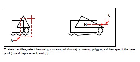
You can change the size of entities by stretching them. When you stretch entities, you must select the entities using either a crossing window or a crossing polygon. You then specify a displacement distance or select a base point and a displacement point. Entities that cross the window or polygon boundary are stretched; those completely within the crossing window or crossing polygon are simply moved.
To stretch an entity
Do one of the following to choose Stretch:
- On the ribbon, choose Home > Stretch (in Edit).
- On the menu, choose Modify > Stretch.
- On the Modify toolbar, click the Stretch tool.
- Type stretch and then press Enter.
In the prompt box, choose Crossing Window or Crossing Polygon.
Select the entities, and then press Enter.
Specify the base point.
Specify the second point of displacement
- On the ribbon, choose Home > Stretch (in Edit).
- On the menu, choose Modify > Stretch.
- On the Modify toolbar, click the Stretch tool.
- Type stretch and then press Enter.
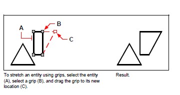
To stretch an entity using grips, you select it to display its grips and then select a grip to make it the active grip. This becomes the base point. Then you move the active grip to a new location. The grip you select depends on the type of entity you’re modifying. For example, to stretch one corner of a rectangle, select the corner point grip. To stretch a line, select an endpoint grip. Not all entities can be stretched using grips.
To stretch an entity using grips
Select the entity.
Click a grip to activate it.
Drag the grip.
Click to release.
Scaling entities
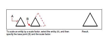
You can change the size of a selected entity by scaling it in relation to a base point. You can change the size of an entity by specifying a base point and a length, which is used as a scale factor based on the current drawing units, or by specifying a scale factor. You can also use a scale factor referenced to a base scale factor, for example, by specifying the current length and a new length for the entity.
To scale a selection set by a scale factor
Do one of the following to choose Scale:
- On the ribbon, choose Edit > Scale (in Modify).
- On the menu, choose Modify > Scale.
- On the Modify toolbar, click the Scale tool.
- Type scale and then press Enter.
Select the entities, and then press Enter.
Specify the base point.
Specify the scale factor.
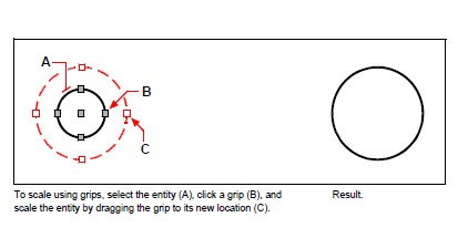
You can also scale some entities using grips. To scale an entity, you select the entity, and then click a grip. You then change the size of the entity by moving the grip. The grip you select depends on the type of entity you’re modifying. For example, to scale a circle, select a quadrant point grip.
To scale an entity using grips:
Select the entity.
Click a grip to select it.
Drag the grip.
Click to release.
Extending entities
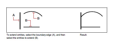
You can extend entities so that they end at a boundary defined by other entities. You can also extend entities to the point at which they would intersect an implied boundary edge. When extending entities, you first select the boundary edges, and then specify the entities to extend, selecting them either one at a time, using the fence selection method, or the projection selection method.
You can extend arcs, lines, two-dimensional polylines, and rays. Arcs, circles, ellipses, lines, splines, polylines, rays, infinite lines, and viewports on a Layout tab can act as boundary edges.
To extend an entity
Do one of the following to choose Extend:
- On the ribbon, choose Edit > Extend (in Modify).
- On the menu, choose Modify > Extend.
- On the Modify toolbar, click the Extend tool.
- Type extend and then press Enter.
Select one or more entities as boundary edges, and then press Enter.
Select the entity to extend.
Select another entity to extend, or press Enter to complete the command.
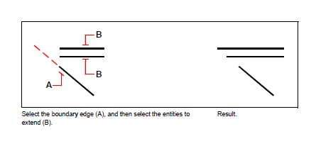
To extend an entity to an implied boundary
Do one of the following to choose Extend:
- On the ribbon, choose Edit > Extend (in Modify).
- On the menu, choose Modify > Extend.
- On the Modify toolbar, click the Extend tool.
- Type extend and then press Enter.
Select one or more boundary edges, and then press Enter.
In the prompt box, choose Edge Mode.
In the prompt box, choose Extend.
Select the entity to extend.
Select another entity to extend, or press Enter to complete the command.
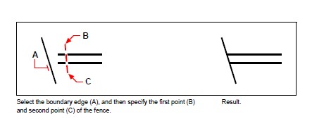
To extend several entities using the fence selection method
Do one of the following to choose Extend:
- On the ribbon, choose Edit > Extend (in Modify).
- On the menu, choose Modify > Extend.
- On the Modify toolbar, click the Extend tool.
- Type extend and then press Enter.
Select one or more boundary edges, and then press Enter.
In the prompt box, choose Fence.
Specify the first point of the fence.
Specify the second point of the fence.
Specify the next fence point, or press Enter to complete the command.
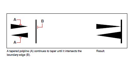
When you extend a wide polyline, its centerline intersects the boundary edge. Because the end of the polyline is always cut at a 90-degree angle, part of the polyline may extend past the boundary edge. A tapered polyline continues to taper until it intersects the boundary edge. If this would result in a negative polyline width, the ending width changes to 0.
Trimming entities
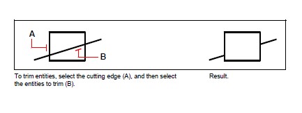
You can clip, or trim, entities so they end at one or more implied cutting edges defined by other entities. You can also trim entities to the point at which they would intersect an implied cutting edge. When trimming entities, you first select the cutting edges and then specify the entities to trim, selecting them either one at a time or using the fence selection method.
You can trim arcs, circles, lines, open two-dimensional and three-dimensional polylines, and rays. Arcs, circles, lines, polylines, rays, infinite lines, and viewports on a Layout tab can act as cutting edges. An entity can be both a cutting edge and one of the entities being trimmed.
To trim an entity
Do one of the following to choose Trim:
- On the ribbon, choose Edit > Trim (in Modify).
- On the menu, choose Modify > Trim.
- On the Modify toolbar, click the Trim tool.
- Type trim and then press Enter.
Select one or more cutting edges, and then press Enter.
Select the entity to trim.
Select another entity to trim, or press Enter to complete the command.
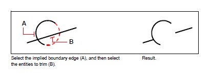
To trim an entity to an implied boundary
Do one of the following to choose Trim:
- On the ribbon, choose Edit > Trim (in Modify).
- On the menu, choose Modify > Trim.
- On the Modify toolbar, click the Trim tool.
- Type trim and then press Enter.
Select one or more cutting edges, and then press Enter.
In the prompt box, choose Edge Mode.
In the prompt box, choose Extend.
Select the entity to trim.
Select another entity to trim, or press Enter to complete the command.
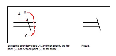
To trim several entities using the fence selection method
Do one of the following to choose Trim:
- On the ribbon, choose Edit > Trim (in Modify).
- On the menu, choose Modify > Trim.
- On the Modify toolbar, click the Trim tool.
- Type trim and then press Enter.
Select one or more cutting edges, and then press Enter.
In the prompt box, choose Fence.
Specify the first point of the fence.
Specify the second point of the fence.
Specify the next fence point, or press Enter to complete the command.
Editing the length of entities
You can change the length of entities or the included angle of arcs. Use any of the following methods to change the length of an entity:
- Dynamically drag the endpoint or angle.
- Specify an incremental length or angle measured from an endpoint.
- Specify the new length as a percentage of the total length or angle.
- Specify a new length or included angle.
You can change the length of arcs, lines, and open polylines.
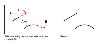
To change the length of an entity by dragging
Do one of the following to choose Edit Length:
- On the ribbon, choose Edit > Edit Length (in Modify).
- On the menu, choose Modify > Edit Length.
- On the Modify toolbar, click the Edit Length tool.
- Type editlen and then press Enter.
In the prompt box, choose Dynamic.
Select the entity you want to change.
Specify the new endpoint or included angle.
© Copyright 2021 BackToCAD Technolgies LLC . All rights reserved. Kazmierczak® is a registered trademark of Kazmierczak Software GmbH. CADdirect 2022 is a trademark of Expert Robotics Inc. Print2CAD and CAD2Print are Trademarks of BackToCAD Technologies LLC. DWG is the name of Autodesk’s proprietary file format and technology used in AutoCAD® software and related products. Autodesk, the Autodesk logo, AutoCAD, DWG are registered trademarks or trademarks of Autodesk, Inc., and/or its subsidiaries and/or affiliates in the USA and/or other countries. All other brand names, product names, or trademarks belong to their respective holders. This website is independent of Autodesk, Inc., and is not authorized by, endorsed by, sponsored by, affiliated with, or otherwise approved by Autodesk, Inc. The material and software have been placed on this Internet site under the authority of the copyright owner for the sole purpose of viewing of the materials by users of this site. Users, press, or journalists are not authorized to reproduce any of the materials in any form or by any means, electronic or mechanical, including data storage and retrieval systems, recording, printing or photocopying.