BackToCAD Technologies LLC | Artificial Intelligence and Software Developing | Clearwater, USA; Stuttgart, Germany | Kazmierczak® Company
Setting and changing options
You can change many of the options that control the program’s behavior and appearance, such as setting the experience level, specifying file paths and default files, con-figuring display features, and configuring how certain features work.
Changing the options on the General tab
In the Options dialog box, the General tab contains settings for experience level and save options. You can also set VBA security.
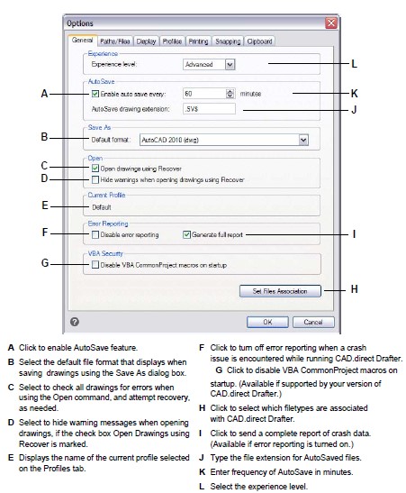
Setting the experience level
You can control which menus and tools are available by setting the experience level. You can choose from the following experience levels:
Beginner Menus and toolbars display only basic commands.
Intermediate Menus and toolbars display most two-dimensional entity creation and modification commands.
Advanced Menus and toolbars display all available commands.
To set the experience level
Do one of the following to choose Options:
- On the ribbon, choose the Application button then choose Options, or choose Tools > Options (in Manage).
- On the menu, choose Tools > Options.
- Type config and then press Enter.
Click the General tab.
Under Experience level, select Beginner, Intermediate, or Advanced.
When you have finished, click OK.
Saving your drawings automatically
To avoid losing data in the event of a power failure or other system error, save your drawing files often. You can configure the program to periodically save your drawings automatically. The Minutes setting determines the interval between automatic saves. The program restarts this interval timer whenever you save the drawing file.
When AutoSave is enabled, the program creates a copy of your drawing. The file is saved in the folder specified in Options > Paths/Files for Temporary Files, with the file extension specified in the AutoSave Drawing Extension box (by default, .SV$).
To set how drawings are saved automatically
Do one of the following to choose Options:
- On the ribbon, choose the Application button then choose Options, or choose Tools > Options (in Manage).
- On the menu, choose Tools > Options.
- Type config and then press Enter.
Click the General tab.
Under AutoSave, select the check box to enable the AutoSave feature, and select the frequency.
If you want to change the default extension assigned to your AutoSave files, type the new extension in AutoSave Drawing Extension.
When you have finished, click OK.
Setting the default SaveAs format
You can control the default file format that you want to display in the Save Drawing As dialog box. For example, if you use the Save As command to save most of your drawings in a legacy file format, you can select that file format as the default so you don’t have to select it each time you save a drawing using the Save As command. This setting has no effect on saving existing or new drawings using commands other than Save As — CADdirect 2022 always saves existing drawings in their current file for-mat and saves new drawings with the most current file format.
To set the default Save As format
Do one of the following to choose Options:
- On the ribbon, choose the Application button then choose Options, or choose Tools > Options (in Manage).
- On the menu, choose Tools > Options.
- Type config and then press Enter.
Click the General tab.
Under Save As, select the default drawing format that displays when using the Save As command. You can always specify a different format in the Save Drawing As dialog box.
When you have finished, click OK.
Setting how drawings are opened
There are several options that determine how drawings are opened in CADdirect 2022. You can specify which file extensions are associated with CADdirect 2022, allowing you to open files such as .dwg files automatically using CADdirect 2022.
Additionally, you can set up CADdirect 2022 to open drawings automatically using the Recover command, for example, if you are a new CADdirect 2022 user and your original drawings were created using different CAD software and those drawings regularly contain errors or damaged data. The Open Drawings using Recover option automatically checks all drawings for errors when using the Open command, and attempts recovery, as needed. Viewing warning messages when opening drawings allows you to know which files are being fixed by CADdirect 2022 and what errors have occurred; however, you can also choose to hide the warnings.
To set how drawings are opened
Do one of the following to choose Options:
- On the ribbon, choose the Application button then choose Options, or choose Tools > Options (in Manage).
- On the menu, choose Tools > Options.
- Type config and then press Enter.
Click the General tab.
To specify the file types that open automatically using CADdirect 2022, click Set Fil Association and make your selections.
If you want to use the Recover command automatically each time you use the Open command, mark the check box for Open Drawings using Recover.
If you want to hide warnings when errors are found in a drawing, mark the check box for Hide Warnings when Opening Drawings using Recover. Errors will still be logged in an ASCII file with an .adt extension.
When you have finished, click OK.
Setting error reporting options
Error reporting occurs when CADdirect 2022 encounters a crash issue. You can specify whether error reporting occurs and whether a full report is generated. It is recommended to generate the full report only if requested for troubleshooting purposes. The completed report of crash data can be up to 100MB in size, and while it contains helpful information for troubleshooting issues, is more likely to fail during transmission due to its file size.
To change the options on the General tab
Do one of the following to choose Options:
- On the ribbon, choose the Application button then choose Options, or choose Tools > Options (in Manage).
- On the menu, choose Tools > Options.
- Type config and then press Enter.
Click the General tab.
If you want to turn off error reporting, mark the check box for Disable Error Reporting.
If you want to generate a full report when error reporting is turned on, mark the check box for Generate Full Report.
When you have finished, click OK.
Disabling VBA CommonProject macros
Each time you start CADdirect 2022, macros are automatically loaded for the Visual Basic Application(VBA) CommonProject. If you do not plan to use VBA, disabling the macros may improve performance. In addition, disabling the macros can enhance security if you are running CADdirect 2022 at a low security level.
To change the options on the General tab
Do one of the following to choose Options:
- On the ribbon, choose the Application button then choose Options, or choose Tools > Options (in Manage).
- On the menu, choose Tools > Options.
- Type config and then press Enter.
Click the General tab.
If you do not want the CommonProject macros to be loaded when you start CADdirect 2022, under VBA Security, click the check box for Disable VBA CommonProject Macros On Startup.
When you have finished, click OK.
Changing the options on the Paths/Files tab
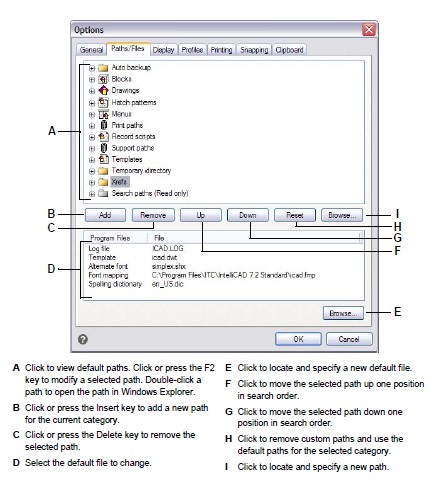
You can specify locations for various file types such as those used for drawings, fonts, and menus in the Options dialog box on the Paths/Files tab. You can even specify multiple paths for the same file type. In addition, you can change the names of the default system files that are used for functions such as font mapping and error logging.
Specifying the user paths
You can enter paths to your CADdirect 2022 directories by selecting them in the Options dialog box. This feature includes directories for drawings, fonts, help, external references, menus, hatch patterns, blocks, print style tables, print output files, temporary files, templates, and color books. CADdirect 2022 searches directories for support files in the following order:
- The CADdirect 2022 program directory.
- The current drawing directory.
- The Windows search path.
- The search path specified in the Options dialog box.
You can enter multiple paths for each item
If, for example, the Drawings item has more than one directory associated with it, click Add to specify additional paths. You can also separate multiple paths with a semicolon if typing them. CADdirect 2022 searches the directories in the order in which they are listed.
To specify a user path
Do one of the following to choose Options:
- On the ribbon, choose the Application button then choose Options, or choose Tools > Options (in Manage).
- On the menu, choose Tools > Options.
- Type config and then press Enter.
Click the Paths/Files tab.
In the upper half of the dialog box, do one of the following:
- Right-click and choose from the shortcut menu of options.
- Click a category to view its search paths, then single-click the path you want to modify, and type the path.
- If you do not know the path or directory name, click Browse, and then browse to the location of the directory you want.
When you have finished, click OK.
Changing the default system files
You can change the default system files, including the log file, default template, alternate font, and font mapping file.
To change a default system file
Do one of the following to choose Options:
- On the ribbon, choose the Application button then choose Options, or choose Tools > Options (in Manage).
- On the menu, choose Tools > Options.
- Type config and then press Enter.
Click the Paths/Files tab.
In the lower half of the dialog box, under Program Files, do one of the following:
- Right-click and choose from the shortcut menu of options.
- Click the file name for the default system file you want to change, and type a new file name.
- If you don’t know the file name, click Browse, and then browse to the location of the file you want.
When you have finished, click OK.
Changing the options on the Display tab
In the Options dialog box, the Display tab contains settings for displaying the command bar, CADdirect 2022 window, menus, mouse actions, and program language.
Setting how the command bar works
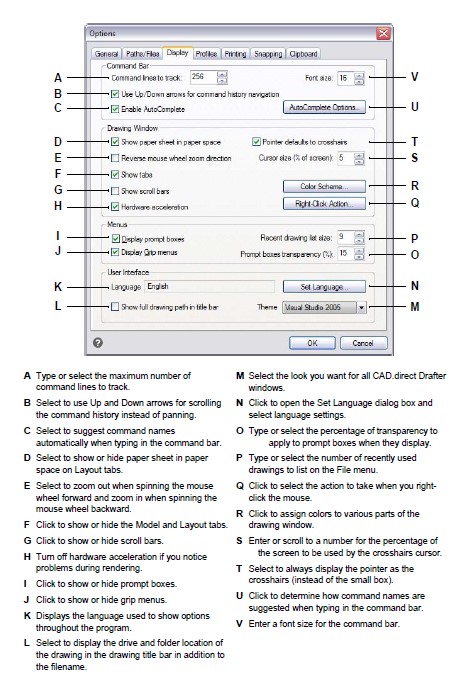
The command bar is a dockable window in which you type CADdirect 2022 commands and view prompts and other program messages. To display the command bar, choose View > Display > Command Bar. To customize how the command bar works, change the options on the Display tab.
To set how the command bar works
Do one of the following to choose Options:
- On the ribbon, choose the Application button then choose Options, or choose Tools > Options (in Manage).
- On the menu, choose Tools > Options.
- Type config and then press Enter.
Click the Display tab.
In Command Lines to Track, enter the desired number of previous command and command prompts that are tracked in the command bar. The default value is 256. You can also display the commands in the Prompt History window by pressing F2. To close the window, press F2 again.
In Font Size, enter the desired font size. The default is 16.
Mark the Use Up/Down Arrows for Command History Navigation check box if you want to scroll the command history text when using the Up and Down arrows on the keyboard. This can be a convenient way to review and even repeat previous commands. If unchecked, using the keyboard arrows pans your view of the drawing.
Use alternate keyboard shortcuts.
For panning, you can use Alt+arrow keys. For scrolling the command history, you can use Ctrl+K and Ctrl+L.
Mark the Enable AutoComplete check box to use the AutoComplete feature when typing commands in the command bar. For more details about AutoComplete, see “Customizing how suggestions display in the command bar” on page 587 in this chapter.
When you have finished, click OK.
Customizing how suggestions display in the command bar
When you type in the command bar, CADdirect 2022 suggests names of matching commands as you type. The suggested names appear in an AutoComplete window that automatically opens when you type and closes when you activate a command.
Using AutoComplete is an efficient way to select commands, and it is also a convenient way to view a list of related commands. For example, if you type “LA” in the command bar to work with layers, all layer-related commands that begin with “LA” display in the AutoComplete window.
In addition to command names, suggestions can include names of external commands, system variables, aliases, and LISP functions. Each name displays with a colored icon that indicates its type:
- Red — CADdirect 2022 command
- Green — External command
- Yellow — System variable
- Blue — LISP function
To customize how suggestions display in the command bar
Do one of the following to choose Options:
- On the ribbon, choose the Application button then choose Options, or choose Tools > Options (in Manage).
- On the menu, choose Tools > Options.
- Type config and then press Enter.
Click the Display tab.
Mark the Enable AutoComplete check box to turn on automatic suggestions of names as you type in the command bar.
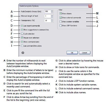
Click AutoComplete Options.
Use a shortcut
Type INPUTSEARCHOPTIONS and then press enter to access autocomplete options directly from the command bar.
In AutoComplete Timeout, enter the number of milliseconds to wait between key-strokes before displaying the AutoComplete window. The higher the number, the longer the delay allowed between keystrokes (the AutoComplete window displays less frequently).
Fast typists usually increase the timeout setting
If the AutoComplete window often conflicts with your typing in the command bar, try setting the number of milliseconds to 1,000 or more.
In Minimum Length of Text, enter the number of letters to be typed in the command bar before displaying the AutoComplete window.
In Transparency, enter the percentage of transparency, between 0 and 50, in which to display the AutoComplete window. The higher the number, the more transparent the window is. Enter zero for an opaque window.
Determine how selection works:
- Mark Use Recent Commands to search for and automatically select a recently used command, when possible.
- Mark Show Suggestions in Command Line to pre-fill the command line with the name as you scroll the list. If turned off, the name does not pre-fill in the command line, however, you can still select the desired name in the AutoComplete window by clicking it or pressing CTRL + Enter.
- Mark Cycle Selection if you want to allow Arrow key scrolling from the end to beginning (and vice versa) in the list.
- Mark Mouse-Over Selection to allow selection by hovering the mouse, and not clicking it, over the desired name.
Mark Show Command Icons to display icons, if available, for each command in the list.
Mark Use Command Line Colors to display the AutoComplete window using the same background and text colors that are selected for the command bar. For more details about selecting command bar colors, see “Setting colors of the main window” on page 591 in this chapter.
Mark which items to include in the list of suggested names: aliases, external commands, system variables, and/or LISP functions. If selected, LISP functions dis-play when you enter a parenthesis, “(“, when first typing.
Click OK.
Click OK.
Setting the main window options
The main CADdirect 2022 window can be customized in many ways to best accommodate your work style. For example, hiding window elements if you do not use them can help increase drawing space in the CADdirect 2022 window.
To set the main window options
Do one of the following to choose Options:
- On the ribbon, choose the Application button then choose Options, or choose Tools > Options (in Manage).
- On the menu, choose Tools > Options.
- Type config and then press Enter.
Click the Display tab.
Mark the Show Paper Sheet in Paper Space checkbox if you want to display a bounded sheet of paper for Layout tabs. When unmarked, the paper sheet does not display.
Mark the Show Tabs checkbox if you want to display the Model tab and Layout tabs in the main window. When unmarked, the tabs do not display, which can be helpful if you only work on the Model tab or if you use the command bar and status bar to switch between tabs.
Mark the Show Scroll Bars checkbox if you want to display the scroll bars on the right side and bottom of the CADdirect 2022 window or viewport. When unmarked, the scroll bars do not display, which can improve performance and can also be helpful if you only use the Pan command to scroll drawings.
Unmark the Hardware Acceleration check box if you experience performance problems or issues during rendering. By default, Hardware Acceleration is turned on, but infrequently it can complicate performance and rendering.
Mark the Pointer Defaults to Crosshairs checkbox if you want to use crosshairs as the default pointer shape (instead of a small box).
In Cursor Size, enter or scroll to a number for the percentage of the screen to be used by the crosshairs cursor. Note that depending on your graphics device, a large percentage can negatively affect display performance.
When you have finished, click OK.
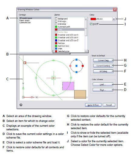
Setting colors of the main window
You can control the color of many aspects of the main drawing window, such as background color, crosshairs color, and more.
To set colors of the main drawing window
Do one of the following to choose Options:
- On the ribbon, choose the Application button then choose Options, or choose Tools > Options (in Manage).
- On the menu, choose Tools > Options.
- Type config and then press Enter.
Click the Display tab.
Click Color Scheme.
In Context, select the area that contains items for which you want to specify colors.
In Items, select the item for which you want to specify a color.
In Colors, select a color or choose Select Color for more options.
Click On/Off to show or hide the item (available only if the selected item can be turned off).
When you have finished, click Apply & Close.
To save and open color schemes
Do one of the following to choose Options:
- On the ribbon, choose the Application button then choose Options, or choose Tools > Options (in Manage).
- On the menu, choose Tools > Options.
- Type config and then press Enter.
Click the Display tab.
Click Color Scheme.
Make any adjustments before you save the settings.
Click Save to save the current color selections as a color scheme file.
Click Load to select a color scheme (.xml or .clr file) and load it.
Click Apply & Close.
Color schemes are an easy way to reuse favorite color settings. If you work on more than one computer, save a color scheme to a file and load the file on another computer.
To restore colors to their defaults
Do one of the following to choose Options:
- On the ribbon, choose the Application button then choose Options, or choose Tools > Options (in Manage).
- On the menu, choose Tools > Options.
- Type config and then press Enter.
Click the Display tab.
Click Color Scheme.
Do one of the following:
- Reset a single item — Select the item you want to revert to the default color, then click Current Item.
- Reset all items in a context — Select the context, then click Current Context. All items in the current context will be reverted to their default colors.
- Reset all colors — Click All Colors. All items in all context will be reverted to their default colors.
Click Apply & Close.
Setting mouse options
Mouse actions can be customized to best accommodate your work style. For example, you may prefer to repeat a recent command when right-clicking the mouse if you do not use shortcut menus.
To set the mouse options
Do one of the following to choose Options:
- On the ribbon, choose the Application button then choose Options, or choose Tools > Options (in Manage).
- On the menu, choose Tools > Options.
- Type config and then press Enter.
Click the Display tab.
Mark the Reverse Mouse Wheel Zoom Direction check box if you want to reverse the zoom direction of the mouse wheel, that is, spin the wheel forward to zoom out and spin it backward to zoom in, This can be especially helpful if you use the mouse with your left hand. When unmarked (the default), you spin the mouse wheel forward to zoom in and spin it backward to zoom out.
To set the action to take when you right-click the mouse in a drawing, click Right-Click Action and choose from the following options:
- No Selection — To repeat the previously used command if you right-click when entities are not selected, choose Repeat Last Command. To display a shortcut menu if you right-click when entities are not selected, select Show Shortcut Menu.
- Entities Are Selected — To repeat the previously used command if you right-click when entities are selected, choose Repeat Last Command. To display a shortcut menu that displays options specific to the selected entities if you right-click, select Show Shortcut Menu. You can right-click anywhere in the drawing with entities selected and the shortcut menu for the selected entities will display.
When you have finished, click OK.
Setting how menus display
The display of menus can be customized, including whether prompt menus and right-click shortcut menus display, whether menus load automatically, and the number of drawing files that display on the File menu.
To set how menus display
Do one of the following to choose Options:
- On the ribbon, choose the Application button then choose Options, or choose Tools > Options (in Manage).
- On the menu, choose Tools > Options.
- Type config and then press Enter.
Click the Display tab.
Mark the Display Prompt Boxes check box if you want to show prompt boxes, which display the same options for commands that display on the status bar and the command bar. Turning prompt boxes off may save screen space and may minimize mouse clicks.
Mark the Display Grip Menus check box if you want grip menus to display when the mouse pauses over a grip that has an associated menu.
In Recent Drawing List Size, enter how many recently opened drawings are listed on the File menu.
When you have finished, click OK.
Setting user interface options
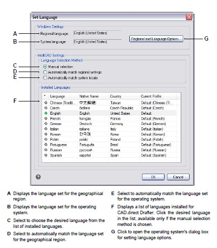
User interface options include how the title bar displays file names, themes that affect how CADdirect 2022 windows look, and the language used to show options throughout CADdirect 2022.
The list of available languages depends on which languages were installed on your computer. If the desired language doesn’t appear in the list, repair or re-install the application with customized settings for the desired language.
To set the user interface options
Do one of the following to choose Options:
- On the ribbon, choose the Application button then choose Options, or choose Tools > Options (in Manage).
- On the menu, choose Tools > Options.
- Type config and then press Enter.
Click the Display tab.
Click Set Language and in Language Selection Method, choose one of the following options:
- Manual selection — Uses the language selected in the Installed Languages list.
- Automatically match regional settings — Matches the language set for the geographical region
- Automatically match system locale — Matches the language set for the operating system.
Click OK.
Mark the Show Full Drawing Path in Title Bar check box if you want to display the drive and folder location of the drawing in the drawing title bar in addition to the filename. When unmarked (the default), only the filename displays in the drawing title bar.
In Theme, select the look you want for all CADdirect 2022 windows.
When you have finished, click OK.
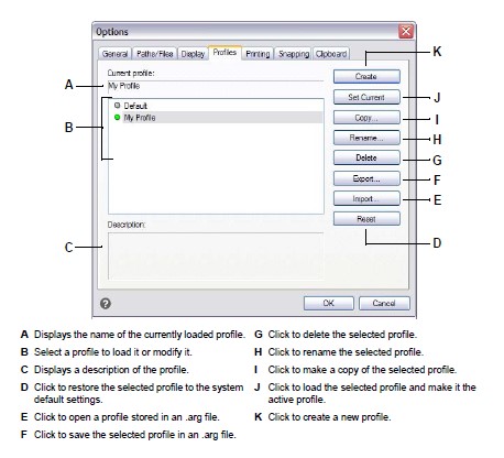
Changing the options on the Profiles tab
CADdirect 2022 allows you to customize the settings that control your drawing environment, and then save and restore those settings in a profile. For example, if you prefer working with custom menus and toolbars, you can save these settings as your own profile.
Profiles can be helpful if you have multiple users with different preferences, or if you are a single user who works on various projects that require unique settings. You can even export your profile and bring it with you when you work on a different computer.
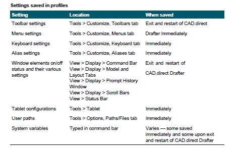
Understanding the settings saved in profiles
Profiles save many settings that control the drawing environment. Once you start using a profile, it automatically tracks and stores changes that you make to your drawing environment.
Some settings are saved immediately, but some require that you exit CADdirect 2022 and then start CADdirect 2022 again. This is because profiles save settings from your computer’s registry and some settings are only saved to the registry when you exit CADdirect 2022.
Creating profiles
Create profiles if you want to save your custom drawing environment settings. This can be helpful if you have two or more drawing environments that you use regularly.
When you create a new profile, the current drawing environment settings are automatically saved with the new profile.
To create a profile
Do one of the following to choose Options:
- On the ribbon, choose the Application button then choose Options, or choose Tools > Options (in Manage).
- On the menu, choose Tools > Options.
- Type config and then press Enter.
Click the Profiles tab.
Click Create.
Enter a name, a description (optional), and then click OK.
In the Options dialog box, click OK.
Make changes to your drawing environment.
CADdirect 2022 automatically saves the settings to the new profile.
Some cases require you to exit and restart CADdirect 2022 before settings are saved with the profile.
This is because profiles save settings from your computer’s registry and some set-tings, such as toolbar settings, are only saved to the registry when you exit CADdirect 2022.
Loading a profile
While you work in CADdirect 2022, you can load the custom settings of any profile. The current profile when you exit CADdirect 2022 is automatically loaded when you start CADdirect 2022 again.
To load a profile
Do one of the following to choose Options:
- On the ribbon, choose the Application button then choose Options, or choose Tools > Options (in Manage).
- On the menu, choose Tools > Options.
- Type config and then press Enter.
Click the Profiles tab.
Select the desired profile.
Click Set Current.
Restoring the default settings
At any time you can return to the default drawing environment settings that were installed with CADdirect 2022.
If the Default profile is unchanged, simply load it to restore the default settings. If the Default profile is deleted or changed, reset an existing profile (one that you no longer need) to replace its contents with the default settings.
To restore default settings using an unchanged Default profile
Do one of the following to choose Options:
- On the ribbon, choose the Application button then choose Options, or choose Tools > Options (in Manage).
- On the menu, choose Tools > Options.
- Type config and then press Enter.
Click the Profiles tab.
Select the Default profile.
Click Set Current.
To restore default settings without using the Default profile
Resetting a profile erases all of the profile’s custom settings
Do this only if you are certain you no longer need the selected profile.
Do one of the following to choose Options:
- On the ribbon, choose the Application button then choose Options, or choose Tools > Options (in Manage).
- On the menu, choose Tools > Options.
- Type config and then press Enter.
Click the Profiles tab.
Select a profile that you no longer need; all of it’s custom settings will be erased. If necessary, create or copy a profile to use for restoring the default settings.
Click Reset.
Managing profiles
Once you start using profiles, you may need to rename, copy, or delete them. Copying a profile is a quick way to create a new profile based on an existing profile.
To rename a profile
Do one of the following to choose Options:
- On the ribbon, choose the Application button then choose Options, or choose Tools > Options (in Manage).
- On the menu, choose Tools > Options.
- Type config and then press Enter.
Click the Profiles tab.
Select the profile you want to rename.
Click Rename.
Make any necessary changes to the name or description, and then click OK.
To copy a profile
Do one of the following to choose Options:
- On the ribbon, choose the Application button then choose Options, or choose Tools > Options (in Manage).
- On the menu, choose Tools > Options.
- Type config and then press Enter.
Click the Profiles tab.
Select the profile you want to copy.
Click Copy.
Enter a new name, a description (optional), and then click OK.
To delete a profile
Do one of the following to choose Options:
- On the ribbon, choose the Application button then choose Options, or choose Tools > Options (in Manage).
- On the menu, choose Tools > Options.
- Type config and then press Enter.
Click the Profiles tab.
Select the profile you want to delete.
Click Delete.
Working with profiles on multiple computers
If you use multiple computers and you like to work with our own drawing environment settings, save time by bringing your profile with you.
On your computer, export your profile to an .arg file. Bring the file with you to the other computer using a disk, E-mail, network, or some other method. When you start working at another computer, simply open and load your profile instead of recreating your preferred drawing environment.
To export a profile to a file
Do one of the following to choose Options:
- On the ribbon, choose the Application button then choose Options, or choose Tools > Options (in Manage).
- On the menu, choose Tools > Options.
- Type config and then press Enter.
Click the Profiles tab.
Select the profile to export.
Click Export.
Specify a location and name for the exported file, and then click Save.
To open a profile from a file
Do one of the following to choose Options:
- On the ribbon, choose the Application button then choose Options, or choose Tools > Options (in Manage).
- On the menu, choose Tools > Options.
- Type config and then press Enter.
Click the Profiles tab.
Click Import.
Locate and select the profile (.arg file), and then click Open.
Make any necessary changes to the name or description, and then click OK. 6 (Optional) To load the imported profile, select it, and then click Set Current.
Changing the options on the Printing tab
In the Options dialog box, on the Printing tab, you can determine several print settings,including the default printer, headers, footers, printer configuration files (PC3 files), and print styles that change the appearance of your printed drawing without modifying the actual entities in your drawing.
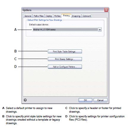
Setting the default printer
A default printer, or output device, is assigned to all new drawings. Select the device you use most often when printing drawings. Later, if needed, you can assign a differ-ent printer for any existing drawing.
To set the default printer
Do one of the following to choose Options:
- On the ribbon, choose the Application button then choose Options, or choose Tools > Options (in Manage).
- On the menu, choose Tools > Options then click the Printing tab or choose File > Print Options.
- Type config, press Enter, then click the Printing tab.
In Default Output Device, select a printer to assign to new drawings.
When you have finished, click OK.
Setting default print styles
Default print style settings affect only specific drawings: new drawings created with-out a template and older drawings when opened (older drawings that were created before print styles were available, for example, before AutoCAD 2000). Drawings that are currently opened are not affected.
For more details about print styles and print style tables, see “Using print styles” on page 474.
To set default print style settings for new drawings
Do one of the following to choose Options:
- On the ribbon, choose the Application button then choose Options, or choose Tools > Options (in Manage).
- On the menu, choose Tools > Options then click the Printing tab or choose File > Print Options.
- Type config, press Enter, then click the Printing tab.
Click Print Style Settings.
Select to use color-dependent or named print style tables for new drawings created without a template.
Select a default print style table to use with new drawings.
For named print style tables, select both the print style to assign to layer zero and to new entities. For color-dependent tables, the print style is BYCOLOR and is not selectable.
Click OK.
When you have finished, click OK.
Specifying a header and footer
You can include information such as a date and time stamp, your name and company name, or other information that you want to appear at the top or bottom of drawings when you print them.
Header and footer settings are set globally for all drawings, although they don’t have to be included with each drawing you print. When printing, in the Print dialog box mark or unmark Print Stamp On accordingly.
To specify a header and footer for all drawings
Do one of the following to choose Options:
- On the ribbon, choose the Application button then choose Options, or choose Tools > Options (in Manage).
- On the menu, choose Tools > Options then click the Printing tab or choose File > Print Options.
- Type config, press Enter, then click the Printing tab.
Click Print Stamp Settings.
Type the content for the header and footer, or select an optional automatic field from the lists. To align text to the left, middle, or right in a header or footer, separate the text with commas.
Click Advanced.
Customize settings for any of the following:
- Orientation Select Horizontal to place the header and footer on the top and bottom of the drawing. Select Vertical to rotate the header and footer 90 degrees on the left and right of the drawing.
- X Offset Enter the distance to offset the header and footer from the edge of the printable area in the x-direction.
- Y Offset Enter the distance to offset the header and footer from the edge of the printable area in the y-direction.
- Offset Relative To Select whether to measure the offset from the edge of the paper or the printable area.
- Font Select the font for the header and footer text.
- Height Select the height for the header and footer text.
- Units Select Inches or Millimeters as the unit of measure for the print stamp X Offset, Y Offset, and Height.
- Add Print Event into Log File Select to include print stamp information in the print log file.
Click OK.
When you have finished, click OK.
Setting up printer configuration files
Printer configuration files (PC3 files) store the printer information you use for specific drawings or layouts. You can add, modify, and delete PC3 files.
For more details about printer configuration files, see “Customizing and reusing print settings” on page 462.
To set up printer configuration files
Do one of the following to choose Options:
- On the ribbon, choose the Application button then choose Options, or choose Tools > Options (in Manage).
- On the menu, choose Tools > Options then click the Printing tab or choose File > Print Options.
- Type config, press Enter, then click the Printing tab.
Click Add or Configure Printers.
To create a new PC3 file, do the following:
- Click Add.
- In the Add Printer Configuration File dialog box, select the desired printer for the new PC3 file.
- Click Continue.
- Select the options you want for the PC3 file. If you don’t select any custom options, a PC3 file will not be created.
- Click OK.
To modify a PC3 file, do the following:
- Select the desired file in the list.
- Click Modify.
- Select the options you want for the PC3 file.
- Click OK.
To delete a PC3 file, select the desired file in the list and click Delete.
Click OK.
When you have finished, click OK.
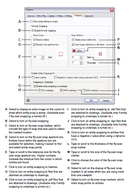
Changing the options on the Snapping tab
In the Options dialog box, on the Snapping tab, you can control how entity snaps work, including fly-over snapping. Fly-over snapping is a visual aid to help you see and use entity snaps more efficiently.
To change the options on the Snapping tab
Do one of the following to choose Options:
- On the ribbon, choose the Application button then choose Options, or choose Tools > Options (in Manage).
- On the menu, choose Tools > Options.
- Type config and then press Enter.
Click the Snapping tab.
Select the options you want.
When you have finished, click OK.
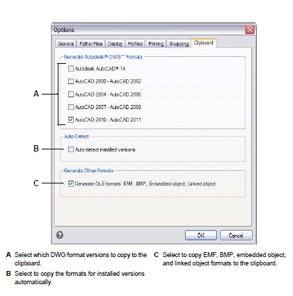
Changing the options on the Clipboard tab
You can control what formats are supported when copying content to the clipboard from CADdirect 2022.
Copying all supported formats to the clipboard impacts performance—it is best to select only the necessary formats.
To change the options on the Clipboard tab
Do one of the following to choose Options:
- On the ribbon, choose the Application button then choose Options, or choose Tools > Options (in Manage).
- On the menu, choose Tools > Options.
- Type config and then press Enter.
Click the Clipboard tab.
Select the options you want.
When you have finished, click OK.
© Copyright 2021 BackToCAD Technolgies LLC . All rights reserved. Kazmierczak® is a registered trademark of Kazmierczak Software GmbH. CADdirect 2022 is a trademark of Expert Robotics Inc. Print2CAD and CAD2Print are Trademarks of BackToCAD Technologies LLC. DWG is the name of Autodesk’s proprietary file format and technology used in AutoCAD® software and related products. Autodesk, the Autodesk logo, AutoCAD, DWG are registered trademarks or trademarks of Autodesk, Inc., and/or its subsidiaries and/or affiliates in the USA and/or other countries. All other brand names, product names, or trademarks belong to their respective holders. This website is independent of Autodesk, Inc., and is not authorized by, endorsed by, sponsored by, affiliated with, or otherwise approved by Autodesk, Inc. The material and software have been placed on this Internet site under the authority of the copyright owner for the sole purpose of viewing of the materials by users of this site. Users, press, or journalists are not authorized to reproduce any of the materials in any form or by any means, electronic or mechanical, including data storage and retrieval systems, recording, printing or photocopying.