BackToCAD Technologies LLC | Artificial Intelligence and Software Developing | Clearwater, USA; Stuttgart, Germany | Kazmierczak® Company
Splitting and combining entities
You can break and combine entities using the following methods:
- Break — Separate a single entity into two parts, removing a portion of the entity in the process.
- Join — Combine two entities into a single entity.
- Explode — Separate a complex entity, such as a block or polyline, into its various component parts.
- Group — Combine multiples entities to behave as a single unit.
Breaking entities
You can break arcs, circles, ellipses, lines, polylines, rays, and infinite lines. When breaking entities, you must specify two points for the break. By default, the point you use to select the entity becomes the first break point; however, you can use the First option to select a break point different from the one that selects the entity.
To break an entity
Do one of the following to choose Break:
- On the ribbon, choose Edit > Break (in Modify).
- On the menu, choose Modify > Break.
- On the Modify toolbar, click the Break tool.
- Type break and then press Enter.
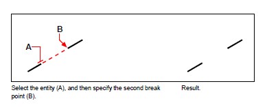
Select the entity.
Specify the second break point.
To select an entity and then specify the two break points
Do one of the following to choose Break:
- On the ribbon, choose Edit > Break (in Modify).
- On the menu, choose Modify > Break.
- On the Modify toolbar, click the Break tool.
- Type break and then press Enter.
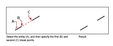
Select the entity.
In the prompt box, choose First.
Specify the first break point.
Specify the second break point.
You can break an entity in two without removing a portion of the entity.
Specify the same point for the first and second break points by typing the at sign (@) and pressing Enter instead of specifying the second break point.
Joining entities
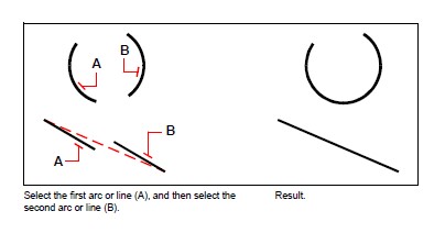
You can join two entities into a single entity. You can join either two lines or two arcs. The two lines must be parallel; the two arcs must share the same center point and radius.
When you join two lines, the farthest endpoints remain at their existing locations; the program draws a new line between these points. Arcs are joined counterclockwise, from the first arc you select to the second.
To join two entities
Do one of the following to choose Join:
- On the ribbon, choose Edit > Join (in Modify).
- On the menu, choose Modify > Join.
- On the Modify toolbar, click the Join tool.
- Type join and then press Enter.
Select the first arc or line.
Select the second arc or line.
Exploding entities
You can convert a complex entity, such as a block or polyline, from a single entity into its component parts. Exploding a polyline, rectangle, donut, polygon, dimension, or leader reduces it to a collection of individual line and arc entities that you can then modify individually. Blocks are converted to the individual entities, possibly including other, nested blocks that composed the original entity.
With the following exceptions, exploding an entity usually has no visible effect on a drawing:
- If the original polyline had a width, the width information is lost when you explode it. The resulting lines and arcs follow the centerline of the original polyline.
- If you explode a block containing attributes, the attributes are lost, but the original attribute definitions remain.
- Colors, linetypes, lineweights, and print styles assigned BYBLOCK may be different after exploding an entity, because they will adopt the default color, linetype, lineweight, and print style until inserted into another block.
To explode an entity
Do one of the following to choose Explode:
- On the ribbon, choose Home > Explode (in Modify) or choose Edit > Explode (in Modify).
- On the menu, choose Modify > Explode.
- On the Modify toolbar, click the Explode tool.
- Type explode and then press Enter.
Select the entities to explode.
Press Enter.
To explode an entity and specify properties of the resulting entities
Do one of the following to choose Xplode:
On the ribbon, choose Edit > Xplode (in Modify).
On the menu, choose Modify > Xplode.
On the Modify toolbar, click the Xplode tool.
Type xplode and then press Enter.
Select the entities to explode.
Choose an option:
- All — Displays prompts for specifying all available properties: color, layer, linetype, and lineweight.
- Color — Enter a color. You can enter an index color, true color, or color from a colorbook.
- Layer — Enter a layer for the resulting entities.
- LType — Enter a linetype for the resulting entities.
- LWeight — Enter a lineweight for the resulting entities.
- Inherit — Explodes selected entities and assigns the same color, layer, linetype, and lineweight properties to sub-entities as the parent entity if the sub-entity layer is 0 and other properties are BYBLOCK.
- Explode — Explodes selected entities in the same way as the Explode command.
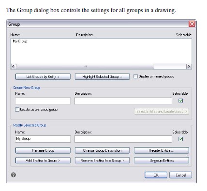
Grouping entities
A group is a collection of entities saved together as one unit. After you select the entities that belong in the group, you can later add more entities, remove entities, and reorder the entities. If necessary, you can also ungroup the entities at any time to work with the entities separately.
Creating groups
When you create a group, you enter a group name and description, and then select the entities for the group.
To create a group
Do one of the following to choose Group:
- On the ribbon, choose Home > Group (in Utilities) or Tools > Group (in Manage).
- On the menu, choose Tools > CADdirect 2022 Explorer > Explore Groups.
- On the Tools toolbar, click the Group tool.
- Type group and then press Enter.
Under Create New Group, enter the name and description of the group.
Click Selectable if you want all entities in the group to be selected,
when you select one entity of the group in the drawing.
Click Select Entities and Create Group.
Select the entities for the group, and then press Enter.
In the Group dialog box, click OK.
You can select entities using groups.
Enter the name of a group in the command bar when selecting entities.
Modifying groups
To modify a group and its entities
Do one of the following to choose Group:
- On the ribbon, choose Home > Group (in Utilities).
- On the menu, choose Tools > CADdirect 2022 Explorer > Explore Groups.
- On the Tools toolbar, click the Group tool.
- Type group and then press Enter.
Select the group you want to modify.
Under Modify Selected Group, do one or more of the following:
- Enter a new name, and then click Rename Group.
- Enter a new description, and then click Change Group Description.
- Select whether you want the group to be selectable in the drawing.
- Click Add Entities to Group, select the entities to add to the group, and then press Enter.
- Click Remove Entities from Group, select the entities to remove from the group, and then press Enter.
In the Group dialog box, click OK.
To change the order of entities in a group
Do one of the following to choose Group:
- On the ribbon, choose Home > Group (in Utilities).
- On the menu, choose Tools > CADdirect 2022 Explorer > Explore Groups.
- On the Tools toolbar, click the Group tool.
- Type group and then press Enter.
Under Modify Selected Group, click Reorder Entities.
In the Reorder Grouped Entities dialog box, select the group you want to reorder.
To see the order of entities in the group, click Highlight. Follow the prompts that display to view the entities one by one.
To reverse the order of all entities in the group, click Reverse Order.
To change the order of specific entities or a range of entities:
- In Remove from Position, enter the current position of the entity.
- In Place to Position, enter the new position of the entity.
- In Number of Entities, enter the number of entities or range of entities to reorder.
- For example, if you are changing the order of one entity, enter 1.
- Click Reorder.
The entities in a group are numbered 0, 1, 2, 3, and so on.
Click OK, and then click OK again.
Ungrouping entities
When you ungroup entities, the entities remain in the drawing, but the group is deleted from the drawing.
To ungroup entities
Do one of the following to choose Group:
- On the ribbon, choose Home > Group (in Utilities).
- On the menu, choose Tools > CADdirect 2022 Explorer > Explore Groups.
- On the Tools toolbar, click the Group tool.
- Type group and then press Enter.
Select the group to delete.
Under Modify Selected Group, click Ungroup Entities.
Click OK.
© Copyright 2021 BackToCAD Technolgies LLC . All rights reserved. Kazmierczak® is a registered trademark of Kazmierczak Software GmbH. CADdirect 2022 is a trademark of Expert Robotics Inc. Print2CAD and CAD2Print are Trademarks of BackToCAD Technologies LLC. DWG is the name of Autodesk’s proprietary file format and technology used in AutoCAD® software and related products. Autodesk, the Autodesk logo, AutoCAD, DWG are registered trademarks or trademarks of Autodesk, Inc., and/or its subsidiaries and/or affiliates in the USA and/or other countries. All other brand names, product names, or trademarks belong to their respective holders. This website is independent of Autodesk, Inc., and is not authorized by, endorsed by, sponsored by, affiliated with, or otherwise approved by Autodesk, Inc. The material and software have been placed on this Internet site under the authority of the copyright owner for the sole purpose of viewing of the materials by users of this site. Users, press, or journalists are not authorized to reproduce any of the materials in any form or by any means, electronic or mechanical, including data storage and retrieval systems, recording, printing or photocopying.