BackToCAD Technologies LLC | Artificial Intelligence and Software Developing | Clearwater, USA; Stuttgart, Germany | Kazmierczak® Company
Using Cartesian coordinates
Many commands in CADdirect require that you specify points as you draw
or modify entities. You can do so by selecting points with the mouse or by typing
coordinate values in the command bar. The program locates points in a drawing
using a Cartesian coordinate system.
Understanding how coordinate systems work
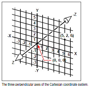
The Cartesian coordinate system uses three perpendicular axes — x, y, and z — to
specify points in three-dimensional space. Every location in a drawing can be represented as a point relative to a 0,0,0 coordinate point, referred to as the origin. To draw a two-dimensional entity, you specify horizontal coordinate positions along the x-axis and vertical coordinate positions along the y-axis. Thus, every point on a plane can be represented as a coordinate pair composed of an x-coordinate and a y-coordinate.
Positive coordinates are located above and to the right of the origin; negative coordinates
are located to the left and below the origin.
When you work in two dimensions, you need enter only the x- and y-coordinates; the
program assumes that the z-axis value is always the current elevation. When you
work in three dimensions, however, you must also specify the z-axis value. When you
look at a plan view of your drawing (a view from above, looking down), the z-axis
extends straight up out of the screen at a 90-degree angle to the xy plane. Positive
coordinates are located above the xy plane, and negative coordinates are below the
plane.
All CADdirect 2022 drawings use a fixed coordinate system, called the World Coordinate System (WCS), and every point in a drawing has a specific x,y,z coordinate
in the WCS. You can also define arbitrary coordinate systems located anywhere in three-dimensional space. These are called user coordinate systems and can be located any-where in the WCS and oriented in any direction.
You can create as many user coordinate systems as you want, saving or redefining them to help you construct three-dimensional entities. By defining a UCS within the WCS, you can simplify the creation of most three-dimensional entities into combinations
of two-dimensional entities.
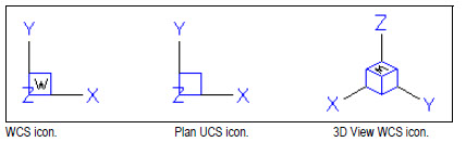
To help you keep your bearings in the current coordinate system, the program displays
a coordinate system icon. When you begin a new drawing, you are automatically in the WCS, indicated by the letter W in the icon. When you display a drawing in plan view, you see the coordinate system icon from the top, with the z-axis directed straight toward you. When you display a three-dimensional drawing in a view other than plan view, the coordinate system icon changes to reflect your new viewpoint.
The visible portions of the axes are the positive directions.
The invisible portions are the negative directions.
The CADdirect UCS icon looks different from the UCS icon in AutoCAD, because it presents more information. Three colors represent the three axes, making it easier for you to recognize the orientation in three-dimensional space:
• x-axis: red
• y-axis: green
• z-axis: blue
If you prefer a single color for the cursor and UCS icon, you can make that change with the config or options command.
Understanding how coordinates display
The current position of the cursor is displayed as x,y,z-coordinates in the status bar and, by default, updates dynamically as you move the cursor. You can toggle the coordinate display to static mode by pressing F6, so that it updates only when you select a point in the drawing.
You can also change the coordinate display to a different dynamic mode that shows the distance and angle (rather than x,y,z-coordinates) when the program displays a rubber-band line. To do this, choose Tools > Drawing Settings and select the Display tab. Under Coordinate Display, select the option for Coordinates In Polar Form For Distance And Angle Selection.
Finding the coordinates of a point
To find the x,y,z-coordinates for a point on an entity, such as the endpoint of a line, select an appropriate entity snap (such as Endpoint) before selecting the entity. If you have no entity snaps set, the x,y-coordinates of the point you specified is displayed, with the z-coordinate equal to the current elevation.
© Copyright 2021 BackToCAD Technolgies LLC . All rights reserved. Kazmierczak® is a registered trademark of Kazmierczak Software GmbH. CADdirect 2022 is a trademark of Expert Robotics Inc. Print2CAD and CAD2Print are Trademarks of BackToCAD Technologies LLC. DWG is the name of Autodesk’s proprietary file format and technology used in AutoCAD® software and related products. Autodesk, the Autodesk logo, AutoCAD, DWG are registered trademarks or trademarks of Autodesk, Inc., and/or its subsidiaries and/or affiliates in the USA and/or other countries. All other brand names, product names, or trademarks belong to their respective holders. This website is independent of Autodesk, Inc., and is not authorized by, endorsed by, sponsored by, affiliated with, or otherwise approved by Autodesk, Inc. The material and software have been placed on this Internet site under the authority of the copyright owner for the sole purpose of viewing of the materials by users of this site. Users, press, or journalists are not authorized to reproduce any of the materials in any form or by any means, electronic or mechanical, including data storage and retrieval systems, recording, printing or photocopying.