BackToCAD Technologies LLC | Artificial Intelligence and Software Developing | Clearwater, USA; Stuttgart, Germany | Kazmierczak® Company
Working with blocks
Usually, blocks are several entities combined into one that you can insert into a drawing and manipulate as a single entity. A block can consist of visible entities such as lines, arcs, and circles, as well as visible or invisible data called attributes. Blocks are stored as part of the drawing file.
Understanding blocks
Blocks can help you better organize your work, quickly create and revise drawings, and reduce drawing file size. Using blocks, you can create a library of frequently used symbols. Then you can insert a symbol as a block rather than redraw the symbol from scratch.
After you create a block from multiple entities, you save it once, which also saves disk space. You insert only multiple references to a single block definition. You can change the block definition to quickly revise a drawing, and then update all instances of the block.
If you insert a block that contains entities originally drawn on layer 0 and assigned color and linetype BYLAYER, it is placed on the current layer and assumes the color and linetype of that layer. If you insert a block that contains entities originally drawn on other layers or with explicitly specified colors or linetypes, the block retains the original settings.
If you insert a block that contains entities originally assigned color and linetype BYBLOCK, and the block itself has the color and linetype BYLAYER, those entities adopt the color and linetype of the layer onto which they are inserted. If the block is assigned an explicit color or linetype, such as red or dashed, those entities adopt those qualities.
A procedure called nesting occurs when you include other blocks in a new block that you are creating. Nesting is useful when you want to combine and include small components, such as nuts and bolts, into a larger assembly and you need to insert multiple instances of that assembly into an even larger drawing.
Creating blocks
You can create blocks in two ways:
- By saving a block for use within the current drawing only.
- By saving the block as a separate drawing file that you can insert into other drawings.
When you create a block, you specify its name, its insertion point, and the entities that compose the block. The insertion point is the base point for the block and serves as the reference point when you later insert the block into a drawing.
The new block you create exists only in the current drawing.
Blocks can also be created using CADdirect 2022 Explorer. For details, see “Working with blocks” on page 253.
To create a block for use within a current drawing
Advanced experience level
Do one of the following to choose Create Block:
- On the ribbon, choose Home>Create Block (in Block) or choose Insert > Create Block (in Block Definition).
- On the menu, choose Draw > Block > Create Block.
- On the Tools toolbar, click the Create Block tool.
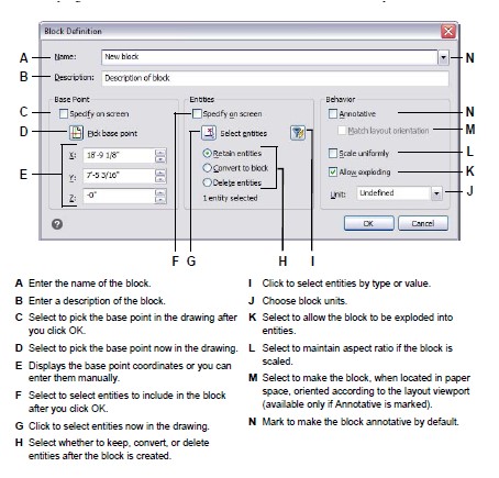
In the Block definition dialog box, enter a name and description for the new block.
Specify the insertion point for the block by doing one of the following:
- Specify on Screen Mark this check box to select the base point in the drawing after you click OK.
- Pick Base Point Click to temporarily close the dialog box immediately, select the base point in the drawing, then return to the dialog box. This option is available only if Specify on Screen is not marked.
- X, Y, and Z Enter the x-, y-, and z-coordinates of the base point. This option is available only if Specify on Screen is not marked.
Select the entities to be combined into the block by doing one of the following:
- Specify on Screen Mark this check box to select the entities in the drawing after you click OK.
- Select entities Click to temporarily close the dialog box immediately, select the entities in the drawing, then return to the dialog box. Or you can click to select entities by type or value. This option is available only if Specify on Screen is not marked.
Select what to do with the entities after the block is created:
- Retain entities Entities selected for the block remain in the drawing.
- Convert to block Entities selected for the block are converted to the block, which remains in the drawing.
- Delete entities Entities selected for the block are removed from the drawing.
Select any of the following options for the block:
- Annotative Determines whether the block is annotative by default. The display and printing of annotative blocks is affected by annotation scaling. If annotative by default, you can determine whether the block, when located in paper space, is oriented automatically according to the layout viewport.
- Scale uniformly Mark this check box to retain the aspect ratio if the block is scaled. Annotative blocks must be scaled proportionately.
- Allow exploding Mark this check box to allow the block to be exploded into separate entities.
- Unit Defines the unit of the block, for example inches or millimeters.
Click OK.
The program adds a new block to the blocks list, with the name you entered for it.
Some users frequently restore original entities after defining a block.
To restore the original entities to the drawing while retaining the new block, type undelete or oops. You might also want to add the Undelete command to a menu or toolbar by choosing Tools > Customize.
Saving blocks
You can create a block as a separate drawing file that you can insert into other drawings.
To save a block as a separate drawing file
Advanced experience level
Do one of the following to choose Save Block To Disk:
- On the ribbon, choose Insert > Save Block to Disk (in Block Definition).
- On the menu, choose Tools > Save Block To Disk.
- On the Tools toolbar, click the Save Block To Disk tool.
- Type wblock and then press Enter.
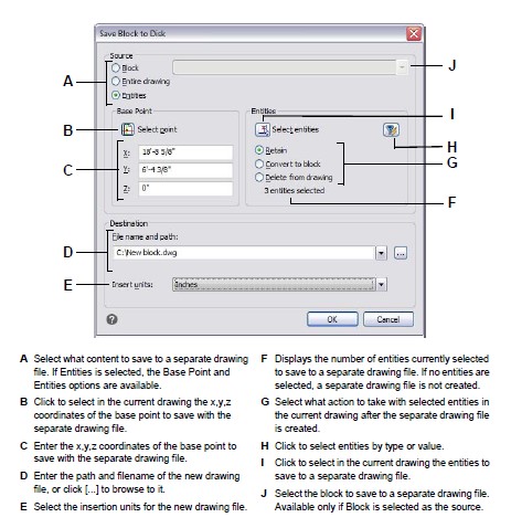
In Source, choose Block, then select the desired block from the list.
In File Name and Path, type the name and path of the destination drawing file you want to create, or click [...] to browse for it.
In Insert Units, select the units used for inserting the separate drawing file.
Click OK.
The program assigns the 0,0,0 coordinate as the insertion base point.
You can change the base point by opening the drawing and redefining the block.
To save the current drawing as a separate drawing file
Advanced experience level
Do one of the following to choose Save Block to Disk:
- On the ribbon, choose Insert > Save Block to Disk (in Block Definition).
- On the menu, choose Tools > Save Block To Disk.
- On the Tools toolbar, click the Save Block To Disk tool.
- Type wblock and then press Enter.
In Source, choose Entire Drawing.
In File Name and Path, type the name and path of the destination drawing file you want to create, or click [...] to browse for it.
In Insert Units, select the units used for inserting the separate drawing file.
Click OK
.
The program assigns the 0,0,0 coordinate as the insertion base point.
You can change the base point by opening the drawing and redefining the block.
To select entities and save them a separate drawing file
Advanced experience level
Do one of the following to choose Save Block to Disk:
- On the ribbon, choose Insert > Save Block to Disk (in Block Definition).
- On the menu, choose Tools > Save Block To Disk.
- On the Tools toolbar, click the Save Block To Disk tool.
- Type wblock and then press Enter.
In Source, choose Entities.
In Base Point, enter the x,y,z coordinates of the base point to save with the separate drawing file, or click to select it directly in the current drawing.
Click and then select the source entities directly in the current drawing. Or you can click to select entities by type or value.
Choose what action to take with selected entities in the current drawing after the separate drawing file is created:
- Retain Keeps the selected source entities in the current drawing.
- Convert to block Converts the selected source entities to a block in the current drawing.
- Delete from drawing Deletes the selected source entities from the current drawing.
- If no entities are selected, a separate drawing file is not created.
In File Name and Path, type the name and path of the destination drawing file you want to create, or click [...] to browse for it.
In Insert Units, select the units used for inserting the separate drawing file.
Click OK.
Inserting blocks
You can insert blocks and other drawings into the current drawing. When you insert a block, it is treated as a single entity. When you insert a drawing, it is added to the cur-rent drawing as a block. You can then insert multiple instances of the block without reloading the original drawing file. If you change the original drawing file, those changes have no effect on the current drawing unless you redefine the block by reinserting the changed drawing.
You can also insert blocks from another drawing into the current drawing, using the CADdirect 2022 Explorer. Both drawings must be open at the same time to do this.
When you insert a block or drawing, you must specify the insertion point, scale, and rotation angle. The block’s insertion point is the reference point specified when you created the block. When you insert a drawing as a block, the program takes the specified insertion point as the block insertion point. You can change the insertion point, however, by first opening the original drawing and redefining the block.
Block settings can also be set before block insertion.
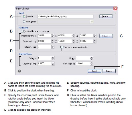
You can specify the insertion point, scale factors, and rotation angle in the Insert Block dialog box before inserting the block. You can also control whether the block is exploded back into its original component entities after insertion. Under Positioning, clear the Position Block When Inserting check box, and specify the appropriate coordinates. If you want to explode the block immediately, select the Explode Upon Insertion check box.
To insert a block
Do one of the following to choose Block:
- On the ribbon, choose Home > Insert Block (in Block) or choose Insert > Insert Block (in Block).
- On the menu, choose Insert > Block.
- On the Draw toolbar, click the Block tool.
- Type ddinsert and then press Enter.
In the Insert Block dialog box, under Insert, click Block Name.
In the Block Name box, select the name of the block you want to insert.
Click Insert.
Specify the insertion point for the block.
Specify the x, y, and z scale factors and the rotation angle, or press Enter to accept the default values.
To insert an entire drawing into the current drawing
Do one of the following to choose Block:
- On the ribbon, choose Home > Insert Block (in Block) or choose Insert > Insert Block (in Block).
- On the menu, choose Insert > Block.
- On the Draw toolbar, click the Block tool.
- Type ddinsert and then press Enter.
In the Insert Block dialog box, under Insert, click From File.
Type the path and the drawing file name, or click Browse to specify the file from the Insert Drawing dialog box, and click Open.
Click Insert.
Specify the insertion point for the block.
Specify the x, y, and z scale factors and the rotation angle, or press Enter to accept the default values.
You can also insert drawings while browsing files on your computer.
If the DRAGOPEN system variable is set to 0, you can drag a .dwg file to the drawing area in CADdirect 2022 to insert it as a block. If DRAGOPEN is set to 1 (the default), the drawing opens in CADdirect 2022.
Redefining blocks
You can redefine all instances of a block within the current drawing. To redefine a block that was created in the current drawing, you create a new block using the same name. You can update all the blocks in the current drawing by redefining the block. If the block was inserted from a separate drawing file that was subsequently updated, reinsert that block to update all other instances in the current drawing.
To redefine a block in the current drawing
Advanced experience level
Do one of the following to choose Create Block:
- On the ribbon, choose Home>Create Block (in Block) or choose Insert > Create Block (in Block Definition).
- On the menu, choose Draw > Block > Create Block. On the Tools toolbar, click the Create Block tool.
- Type block and then press Enter.
In Name, select the name of the block you want to redefine from the list.
Specify the insertion point for the block.
Select the entities for the block.
Make selections about the behavior.
Click OK.
When prompted, choose Yes to redefine the block. The block is redefined, and all instances of the block in the drawing are updated.
To restore the original entities to the drawing while retaining the new block, type undelete or oops.
You can update all instances of a block inserted from a separate drawing by reinserting the drawing.
Editing blocks in-place
After a block is inserted in a drawing, it can be edited directly in CADdirect 2022, and the source block and all references to the block are updated automatically. Editing in-place is an easy way to make changes to a block without having to locate and load it.
To edit blocks in-place
Do one of the following:
- On the ribbon, choose Insert > Edit Reference in Place (in Reference).
- On the menu, choose Tools > Edit Block or X-Ref In-Place > Edit In-Place.
- Type refedit and then press Enter.
At the prompt, select the block you want to edit. The Reference Edit dialog box displays.
In Reference Name, select the block you want to edit.
Select the Settings tab and select from the following options:
- Create Unique Layer, Style and Block Names Select to create unique names for layers, styles, and blocks that you change. A prefix is added to the original name of a changed layer, style, or block. Names of unchanged layers, styles, and blocks do not change.
- Display Attribute Definitions for Editing Select to hide attributes and display attribute definitions while editing. After saving, changed attribute definitions affect new block insertions only. Existing blocks are not affected.
Click OK.
Make changes to the contents of the block.
To add an entity from the drawing to the block, select the entity and do one of the following:
- Choose Tools > Edit Block or X-Ref In-Place > Add to Working Set.
- Type refset, press Enter, then choose Add.
To remove an entity from the block, select the entity and do one of the following:
- Choose Tools > Edit Block or X-Ref In-Place > Remove from Working Set.
- Type refset, press Enter, then choose Remove.
When you’re finished editing the block, do one of the following:
- Choose Tools > Edit Block or X-Ref In-Place > Close Reference.
- Type refclose and then press Enter.
Choose Save to save changes or Discard to cancel changes.
If changes are saved, all instances of the block are updated in the current drawing.
Exploding blocks
You can explode an inserted block to its original component entities. When you explode a block, only that single instance of the block is affected. The original block definition remains in the drawing, and you can still insert additional copies of the original block. If you explode a block that contains attributes, the attributes are lost, but the original attribute definitions remain.
Exploding dissociates component entities to their next simplest level of complexity; blocks or polylines in a block become blocks or polylines again.
To explode a block
Do one of the following to choose Explode:
- On the ribbon, choose Home > Explode (in Modify) or choose Edit > Explode (in Modify).
- On the menu, choose Modify > Explode.
- On the Modify toolbar, click the Explode tool.
- Type explode and then press Enter.
Select the block.
Press Enter.
© Copyright 2021 BackToCAD Technolgies LLC . All rights reserved. Kazmierczak® is a registered trademark of Kazmierczak Software GmbH. CADdirect 2022 is a trademark of Expert Robotics Inc. Print2CAD and CAD2Print are Trademarks of BackToCAD Technologies LLC. DWG is the name of Autodesk’s proprietary file format and technology used in AutoCAD® software and related products. Autodesk, the Autodesk logo, AutoCAD, DWG are registered trademarks or trademarks of Autodesk, Inc., and/or its subsidiaries and/or affiliates in the USA and/or other countries. All other brand names, product names, or trademarks belong to their respective holders. This website is independent of Autodesk, Inc., and is not authorized by, endorsed by, sponsored by, affiliated with, or otherwise approved by Autodesk, Inc. The material and software have been placed on this Internet site under the authority of the copyright owner for the sole purpose of viewing of the materials by users of this site. Users, press, or journalists are not authorized to reproduce any of the materials in any form or by any means, electronic or mechanical, including data storage and retrieval systems, recording, printing or photocopying.